1 scope of manual, 2 description, Figure 1. ra 19-4c rack adapter i/o connector – KEPCO HSF 1500W Series (all models) Operator Manuals User Manual
Page 3: Table 1. rear connector pin assignments, Introduction 1.1, Scope of manual, Description, Ra 19-4c rack adapter i/o connector, Rear connector pin assignments
HSF 1500W 022613
1
1.
INTRODUCTION
1.1
SCOPE OF MANUAL
This Operator's Manual covers the installation and operation of the Kepco HSF 1200W/1500W
Series of Switching Power Supplies. For service information, write directly to: Kepco Inc., 131-38
Sanford Avenue, Flushing, New York, 11355, U.S.A. Please state Model Designation and Serial
Number of your HSF Power Supply (see nameplate of the unit).
1.2
DESCRIPTION
The Kepco HSF1500 Watt Series are hot swappable, high frequency switching, plug-in power
supplies. Metered models (M suffix) are completely interchangeable with the non-metered HSF
Series. Three models may be selected for outputs of 24V (1200W), 36V or 48V (1500W). They
employ forward conversion and power factor correction and are designed to operate in a fault tol-
erant power system with a nominal a-c input of 100V a-c to 240V a-c (input voltage range 85 to
265V a-c), 50-60Hz (input frequency range 47-440Hz). A built-in current balancing circuit and OR-
ing diodes allow configuration for hot-swap and parallel-redundant N+1 operation.
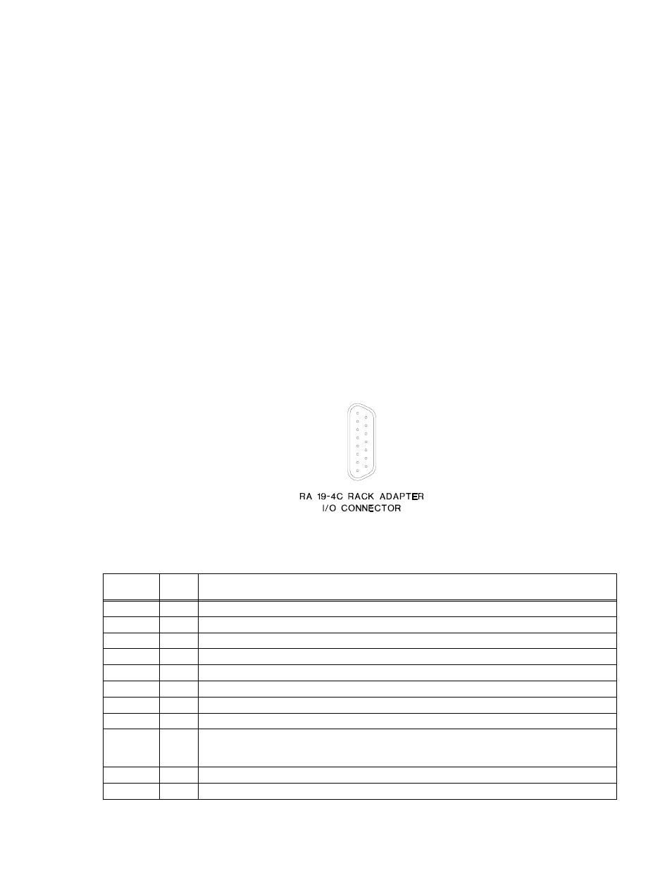
These power supplies are designed to be used with Kepco's Series RA 19-4C rack adapters. The
RA 19-4C rack adapter accepts up to four 1200W (24V) or 1500W (36V, 48V) modules. All input/
output connections are through a 24-pin connector that plugs in to the rack adapter. All external
connections are made through the rack adapter’s I/O connector (see Figure 1).
An optional meter (M suffix) provides digital indication of voltage or current (switch selectable)
from the front panel. An optional current sense resistor (C suffix) allows external current monitor-
ing within 3% (contact Kepco if greater accuracy is required). RoHS-compliant models indicated
by HSF* (e.g., HSF 24*50M).
FIGURE 1. RA 19-4C RACK ADAPTER I/O CONNECTOR
TABLE 1. REAR CONNECTOR PIN ASSIGNMENTS
Signal
Name
Pin
Function
Output +
1, 2, 4
DC output (+) applied to load.
Output –
3, 5, 6
DC Output (–) applied to load.
IMON+
8
Current Monitor+ (used on C and M suffix only).
NO
10
Normally Open contact of alarm relay, referenced to AL COM, pin 14 (see PAR. 3.8.2).
IMON–
11
Current Monitor– (used on C and M suffix only).
–COM
12
–Signal Common provides return for REF, pin 15, and RV, pin 18, signals.
NC
13
Normally Closed contact of alarm relay, referenced to AL COM, pin 14 (see PAR. 3.8.2).
AL COM
14
Common contact of alarm relay (see PAR. 3.8.2).
REF
15
Reference voltage. When used with RV, pin 18, allows all output voltages of paralleled slave supplies to be
controlled by one voltage adjustment of a master power supply. When REF is connected to RV, the front
panel Vadj control determines output voltage. Connections are made via DIP switches (see PAR. 3.1).
+PF
16
+Power Fail of open-collector alarm circuit. Used with –PF, pin 19 (see PAR. 3.8.2).
CSB
17
Current Share Bus - Used whenever several power supplies are connected in parallel (see PAR. 5.).
3042866
7
8
2
4
5
6
3
1
+IMON
CSB
-RC
ALARM (NO)
ALARM (NC)
REF
+PF
(NOT USED)
15
9
12
13
14
11
10
+RC
-IMON
(NOT USED)
ALARM (COM)
-PF
-COM
RV