Figure 7. connections for remote voltage control, 6 remote on-off, 7 protection circuits – KEPCO HSF 1500W Series (all models) Operator Manuals User Manual
Page 11: 1 overvoltage and overtemperature protection, Remote on-off, Protection circuits, Overvoltage and overtemperature protection, Connections for remote voltage control, R. 3.6), 7a. sugg
HSF 1500W 022613
9
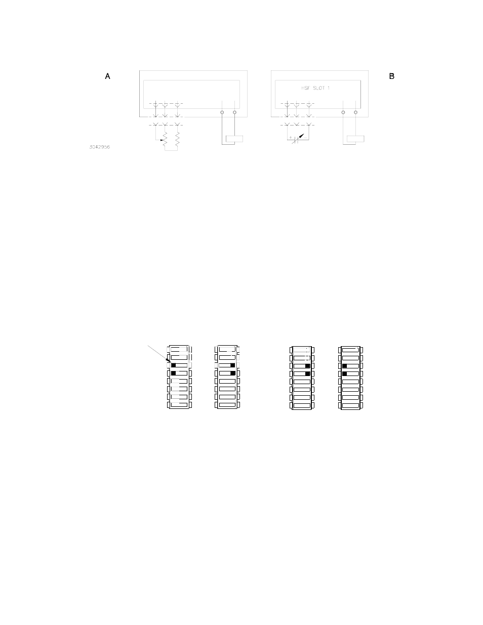
FIGURE 7. CONNECTIONS FOR REMOTE VOLTAGE CONTROL
3.6
REMOTE ON-OFF
When power is ON at the source, the output may be turned ON or OFF using the ±RC signals if
the remote ON-OFF feature is enabled. Note that when remote ON-OFF is enabled, the RESET
OUTPUT switch does not function. Remote ON-OFF is enabled by setting DIP switch positions 3
and 4 as shown in Figure 8B. The +RC and –RC signals (at the rack adapter I/O connector, pins
15 and 8, respectively) then turn the unit on or off. These pins accept a logic level (2.4V to 24V
“high” and 0.0 to 0.4V “low”), or a contact closure. When the ±RC pins are open, using either a
mechanical switch or a high level logic signal, the power supply output is cut OFF. When the ±RC
pins are shorted, the output returns to within specifications. At low level logic, the maximum
source current is 1.6mA and at high level the sink current is 1.0mA. Positions 3 and 4 of both DIP
switches must be restored to the factory default setting (Figure 8A) if remote ON-OFF is not used.
The ±RC pins are isolated from DC output pins.
FIGURE 8. DIP SWITCH SETTINGS FOR USING RESET BUTTON OR REMOTE ON-OFF
3.7
PROTECTION CIRCUITS
The following protection features are implemented in the power supplies: overvoltage and over-
temperature (PAR. 3.7.1), overcurrent (PAR. 3.7.2), fan failure (PAR. 3.7.3), and undervoltage
(PAR. 3.7.4). The power supply provides a configurable visual alarm (see PAR. 3.8.1) as well as
an option to use either relay contacts or logic levels for alarm signals (see PAR. 3.8.2)
3.7.1 OVERVOLTAGE AND OVERTEMPERATURE PROTECTION
When the output voltage of the power supply increases beyond the specified values (see Table 2),
the output is cut OFF and the fan turns OFF. To restart (reset) the unit, press and release the
OUTPUT RESET switch on the front panel or, if the remote on/off feature is in use (see PAR. 3.6),
open connection between the RC pins and then reconnect the pins. The unit may also be
restarted by turning the POWER ON/OFF switch to OFF, waiting 30 seconds, then setting the
POWER switch to ON.
REMOTE VOLTAGE
CONTROL USING
EXTERNAL RESISTANCE
RA 19-4C
RA 19-4C
HSF SLOT 1
RV REF -COM
10
2
12
I/O 1
R
(SEE TABLE 4
FOR VALUES)
LOAD
J2
RV REF -COM
J2
I/O 1
10
12 2
VOLTAGE
SOURCE
(SEE NOTE)
LOAD
REMOTE VOLTAGE
CONTROL USING
EXTERNAL VOLTAGE
NOTE: SEE TABLE 4 FOR
MINIMUM VALUE.
- +
- +
3042877
3
3 +RC
+RC 3
3
SW1
-RC 4
4
SW2
4
4 -RC
OFF
ON
OFF
ON
(FACTORY DEFAULT)
USE FRONT PANEL
RESET BUTTON
A
B
(LOGICAL LEVEL OR
MECHANICAL SWITCH)
USE REMOTE ON-OFF
3
3
SW2
SW1
4
4
ON
OFF
OFF
ON
3 +RC
4 -RC
+RC 3
-RC 4
TAB