8 is a simplifie – KEPCO BOP 1KW-MG Operator Manual, Firmware Ver.4.08 to 4.11 User Manual
Page 57
BOP HIPWR 070212
2-19
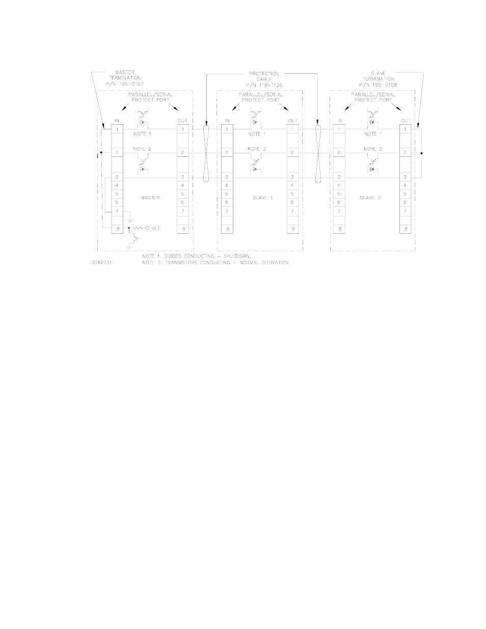
FIGURE 2-8. TYPICAL MASTER/SLAVE PROTECTION INTERCONNECTIONS
Upon startup, PAR/SER PROT IN PORT pin 8 of the master goes low, and stays low until all
slaves are powered up. Normal power up of a unit causes the transistor connecting PAR/SER
PROT IN PORT pin 2 and PAR/SER PROT OUT PORT pin 2 to conduct. The transistors of all
units are connected in series, effectively shorting out all the shutdown diodes (the shutdown
diodes of all units are also connected in series) connecting PAR/SER PROT IN PORT pin 1 and
PAR/SER PROT OUT PORT pin 1. After all the units are powered up and operating normally,
the low at PAR/SER PROT IN PORT pin 8 changes to high, but the conducting transistors keep
the voltage at pin 8 low and the diodes are cut off. If a fault occurs, the transistor between PAR/
SER PROT IN PORT pin 2 and PAR/SER PROT OUT PORT pin 2 of the defective unit is cut off,
allowing current to flow through the shutdown diodes. This develops internal shutdown signals
that shut down all units.
2.8.3
CONFIGURING PARALLEL, SERIES, 2 X 2 OR 3 X 2 COMBINATIONS
1. To configure a unit to be designated as a slave proceed as follows:
a. Turn on power only to the unit to be designated as a slave.
b. From the power-up screen press
%
to enter the General Setup Menu. Highlight Series/
Parallel and press
!
to view the Multiple Units menu (see Table 2-12). If required, enter
password (see PAR. 3.2.4.4) before continuing.
c. From the Multiple Units menu, highlight Configuration (use ADJUST control or the
Y
or
U
keys) and press
!
to modify. When prompted, enter ADMIN2 password (see PAR.
3.2.4.4). Select Series, Parallel, Master 2X2 or Master 3X2 and press
$
to apply
the change.