2 voltage/current mode control, 1 fixed gain using external reference control, Voltage/current mode control -39 – KEPCO BOP 1KW-MG Operator Manual, Firmware Ver.4.08 to 4.11 User Manual
Page 103: Fixed gain using external reference control -39, R. 3.4.3.1, Nd 3.4.3), R. 3.4.3.1 for, R. 3.4.3.1), Ar. 3.4.2), 2, Ar. 3.4.3)
BOP HIPWR 070212
3-39
maximum delay of 200 mS and the STANDBY indicator goes on. Depressing the STANDBY key
or sending the OUTP ON command via the remote interface restores the unit to the previous
state and the STANDBY indicator goes off.
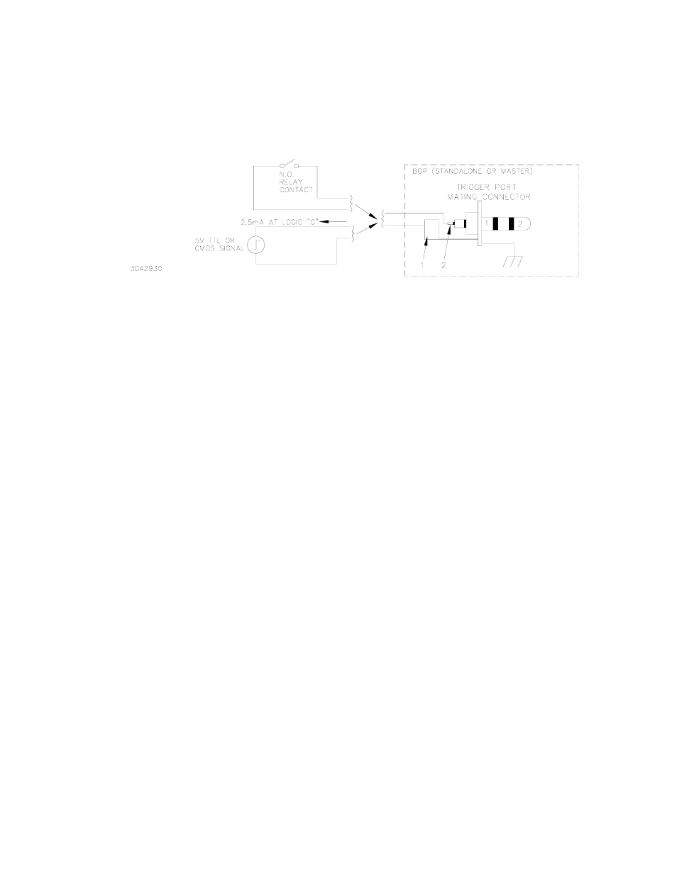
FIGURE 3-15. REMOTE STANDBY, STANDALONE OR MULTIPLE UNITS
3.4.2
VOLTAGE/CURRENT MODE CONTROL
The mode of operation, voltage or current, can be programmed externally by applying a signal
at pin 2, referenced to pin 9, of the Analog I/O port. Applying a TTL logic 1 (or open circuit) pro-
grams the unit to voltage mode. Applying a TTL logic 0 (or short) programs the unit to current
mode.
To be functional this feature must first be configured from the front panel. From the power-up
screen press
$
to enter the Analog Remote Setup menu (see Table 3-15). Highlight External
Mode, then press
!
, highlight Enable and press
$
. Press
%
to apply the changes (without
saving for power-up) and exit to the power-up screen or
#
to abort. The Save/Recall feature
(PAR. 3.3.8) can also be used to restore this setting upon power-up.
3.4.3
CONTROLLING THE OUTPUT USING THE BOP AS A POWER AMPLIFIER
The BOP can function as a power amplifier by means of the External Reference input at the
Analog I/O port. This analog signal controls the main channel of the BOP. To use the BOP as a
power amplifier see the following instructions for using the external reference: PAR. 3.4.3.1 for
fixed gain, PAR. 3.4.3.2 for variable gain by establishing the maximum full scale output.
3.4.3.1
FIXED GAIN USING EXTERNAL REFERENCE CONTROL
The main channel of the BOP, voltage in voltage mode, and current in current mode, can be
controlled by an external reference voltage, 0 to ±10V applied at pin 11, referenced to pin 10, of
the Analog I/O port. The input impedance for this signal is 20K ohms. This feature is enabled as
follows:
1. From the power-up screen, press
$
, highlight Reference Input and press
!
. Highlight
External and press
$
to save. Then press
%
to apply the changes (without saving for
power-up) and exit. NOTE: This setting can be saved for power-up only by using the pass-
word-protected Power-up Settings menu (see {PAR. 3.3.7), otherwise internal references
are used for both main and protection channels upon power-up.