Draining unvented installations, 6gis – A.O. Smith 30 User Manual
Page 56
Draining
56
Instruction manual SGS
6
gis
Note
In the above diagram, there is a non-return valve in the station. This may
only be used in closed (pressure) systems. In systems with drain back, it is
prohibited to fit a non-return valve in the solar heating system.
6.2
Draining unvented
installations
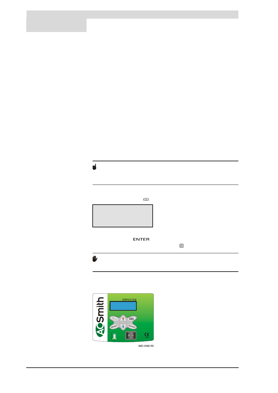
1. Activate the MENU with
.
2. Position the cursor in front of OFF.
3. Confirm OFF with
.
4. Wait until the fan has stopped. The symbol is then dimmed.
Caution
Failure to wait until the fan stops purging can cause damage to the
appliance.
5. Switch the appliance OFF (position 0) using the ON/OFF switch on the
control panel.
Legend
Only applicable numbers are mentioned.
1. pressure-reducing valve (mandatory if the mains
water pressure exceeds 8 bar)
3. T&P valve (mandatory)
4. stop valve (recommended in pipe C and mandatory in
pipe A)
5. non-return valve (mandatory)
6. circulation pump (optional)
9. drain valve
10. manual gas valve (mandatory)
11. service stop valve (recommended)
12. temperature gauge (recommended)
13. condensation drainage (mandatory)
14. hot water draw-off points
16. expansion vessel (mandatory)
17. 3-way aeration valve (recommended)
18. water tank
19. float valve
23. pressure valve (mandatory)
26. air bleed (mandatory)
37. combined Q/T sensor (optional)
38. solar heating system pump station (modulating -
mandatory)
A. cold water supply
B. hot water supply
C. circulation pipe
D. gas supply
E. overflow pipe
F. heat exchanger supply
G. heat exchanger return
H. overflow safety
S1.collector sensor (mandatory)
S2.tank sensor (mandatory)
S3.top tank sensor (mandatory)
S4.heat exchanger discharge sensor (optional)
MENU
»OFF
^ ON
È WEEK PROGRAM