The appliance's heating cycle, 2gis – A.O. Smith 30 User Manual
Page 14
Working principle of the appliance
14
Instruction manual SGS
2
gis
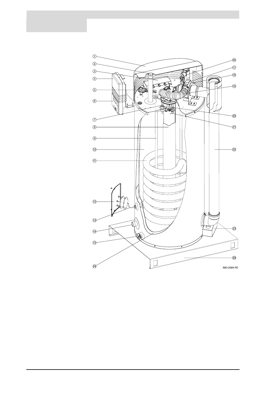
Cut-away view of the appliance
2.3
The appliance's
heating cycle
The net water temperature (T
net
) in the appliance is used to regulate when both
the gas burner and the solar heating system are started and stopped. T
net
is the
curve shown in the figure. The controller uses two measured values to calculate
this temperature: T
1
(7) and T
2
(13). In addition, temperatures S
1
, S
2
and S
3
are used by the controller of the solar heating system. S
1
is measured in the
solar collector. S
2
is located between the inlet and outlet of the heat exchanger
of the storage tank. S
3
is measured at the top side of the storage tank.
Depending on whether or not hot water is being drawn off, hot water can be
pumped from the storage tank to the appliance. This happens when S
3
is 5
o
C
higher than T
net
. Water is then pumped from the appliance to the storage tank,
causing hot water to flow from the storage tank into the appliance. The pump
switches off as soon as S
3
equals T
net
.
The other settings that govern the control behaviour are:
Legend
Only applicable numbers are
mentioned.
1. cover
2. hot water outlet
3. electrical connector block
4. electronic controller
5. pressure switch
6. control panel
7. temperature sensor T
1
8. combustion chamber
9. anode
10. tank
11. heat exchanger
12. inspection and cleaning opening
13. temperature sensor T
2
14. cold water inlet
15. drain valve
16. gas control
17. burner
18. fan
19. air supply hose
20. hot surface igniter
21. flame probe
22. chimney pipe
23. siphon
24. insulation layer
29. pallet