Safety of the installation, Pressure switch, Flame probe – A.O. Smith 30 User Manual
Page 17
Instruction manual SGS
17
gis
2.4.5
Fan
The fan (18) provides an optimum air supply when there is a heat demand. As
a safety feature, the fan ensures that any gases present in the combustion
chamber are removed, both before and after combustion. We refer to this as
pre- and post-purge.
The fan speed is continuously monitored by the electronic controller (4). The
electronic controller takes control if the speed of rotation varies too much from
the set value.
2.4.6
Pressure switch
The pressure switch ensures the discharge of flue gases and the supply of
incoming air during the pre-purge and normal running of the appliance. The
default state of the pressure switch is open. When sufficient pressure difference
is reached, the pressure switch closes. However, in the event of a fault, the
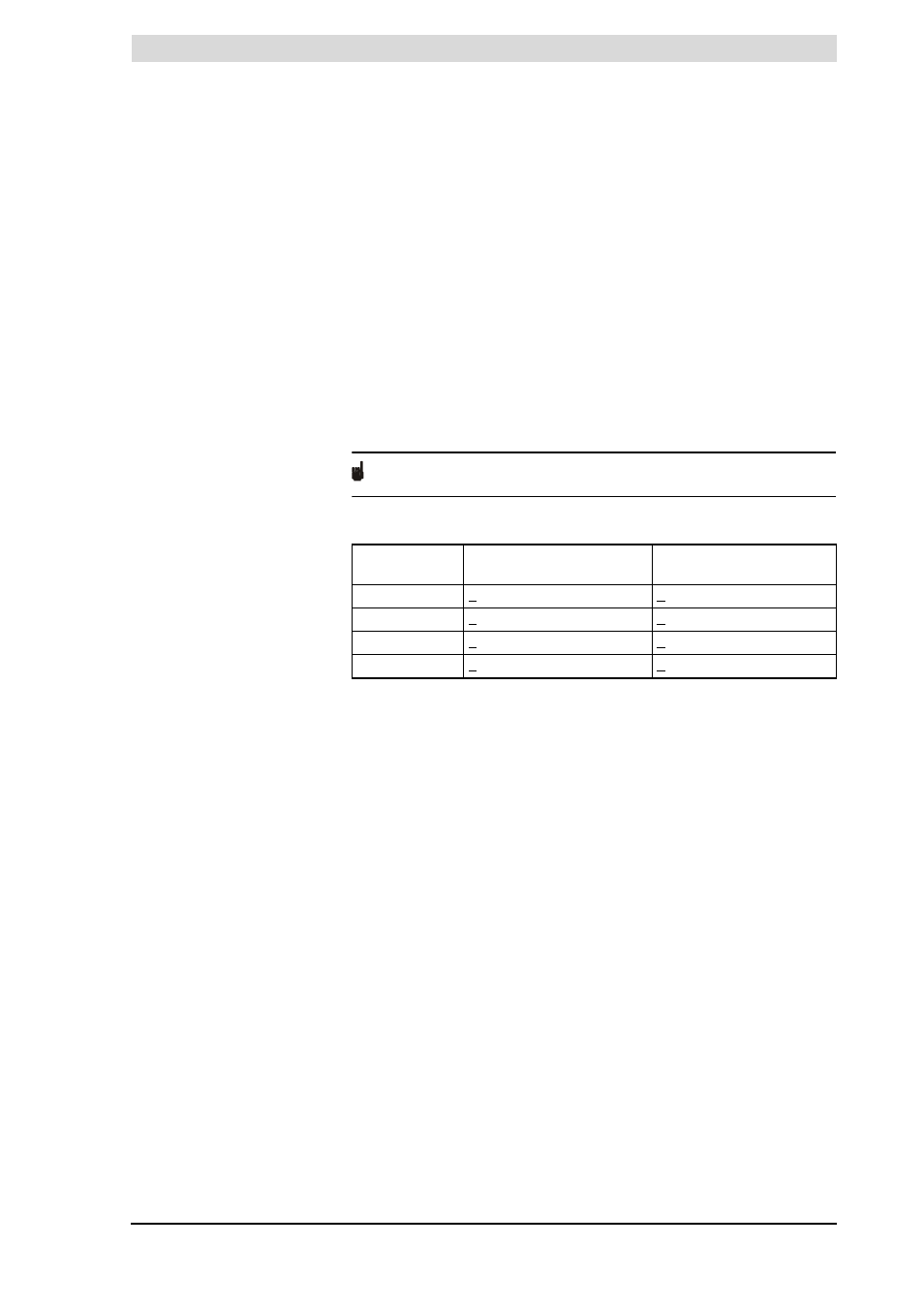
pressure switch is tripped open, and the heating cycle is interrupted. The table
shows the trip point per appliance.
Note
The trip point of the pressure switch is not adjustable.
Pressure switch trip points
2.4.7
Flame probe
To ensure that no gas can flow when there is no combustion, the water heater
is fitted with a flame probe (21). The electronic controller uses this probe to
detect the presence of a flame, by means of ionisation detection. The electronic
controller closes the gas control the instant it detects that there is a gas flow but
no flame.
2.5
Safety of the
installation
In addition to the appliance's standard built-in safety monitoring, the appliance
must also be protected by an expansion vessel, expansion valve, pressure
reducing valve, non-return valve and a T&P valve.
The use of an expansion vessel, expansion valve and/or pressure reducing
valve depends on the type of installation: unvented or vented.
2.5.1
Unvented installation
With an unvented installation, an expansion valve valve and expansion vessel
prevent the buildup of excessive pressure in the tank. This prevents damage
being caused to the enamelled coating (in the appliance) or to the tank. A non-
return valve prevents excessive pressure buildup in the water supply system.
This valve also prevents water from flowing backwards from the tank into the
cold water supply system. The pressure reducing valve protects the installation
against an excessively high water supply pressure (> 8 bar). These components
are fitted to the cold water pipe
(3.6 "Water connections, Vented")
.
Appliance
Closing pressure
difference
Opening pressure
difference
SGS 28
> 635 Pa
< 605 Pa
SGS 30
> 855 Pa
< 825 Pa
SGS 50
> 885 Pa
< 855 Pa
SGS 60
> 1085 Pa
< 1055 Pa