Parallel connections – A.O. Smith 30 User Manual
Page 35
Instruction manual SGS
35
is
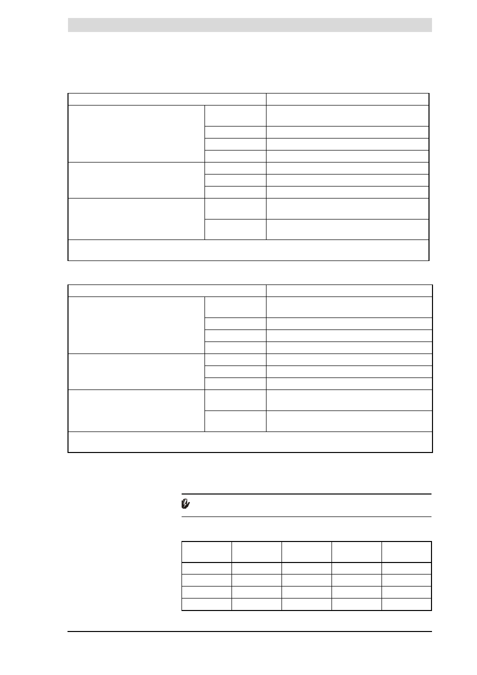
Concentric wall flue terminal specifications C13
Concentric roof flue terminal specifications C33
3.10.4
Parallel connections
The table states the maximum pipe lengths for parallel systems. The maximum
pipe length depends on the chosen diameter.
Warning
Install flue component pipe runs with a run-off of 5 mm per metre.
Flue gas outlet requirements for parallel systems
Specification
Description
Wall flue terminal set:
•
1X Wall flue terminal (incl. wall flange
& clamping ring)
•
1X Pipe 500mm
•
1X Bend 90°
Art. No.
SGS 28
SGS 30-50-60
0302 515
1
0302 504
1
Construction
Concentric
Manufacturer
Muelink & Grol
Model
M2000 MDV SEC
Pipe material
Construction
Concentric
Flue
Thick-walled aluminium with lip ring seal
Air supply
Thin-walled galvanised sheet steel
Pipe diameters
Flue
SGS 28
SGS 30-50-60
Ø 80 mm
Ø 100 mm
Air supply
SGS 28
SGS 30-50-60
Ø 125 mm
Ø 150 mm
(1)
No other wall flue terminal is permitted. Use this item number to order the wall conduit set from supplier,
manufacturer or wholesaler.
Specification
Description
Roof flue terminal set:
•
1X Wall flue terminal (incl. clamping
ring)
•
1X Pipe 1000mm
•
1 X Mounting flange
Art. No.
SGS 28
SGS 30-50-60
0305 042
1
0304 423
1
Construction
Concentric
Manufacturer
Muelink & Grol
Model
M2000 DDV HR-C
Pipe material
Construction
Concentric
Flue
Thick-walled aluminium with lip ring seal
Air supply
Thin-walled galvanised sheet steel
Pipe diameters
Flue
SGS 28
SGS 30-50-60
Ø 80 mm
Ø 100 mm
Air supply
SGS 28
SGS 30-50-60
Ø 125mm
Ø 150 mm
(1)
No other wall flue terminal is permitted. Use this item number to order the wall conduit set from supplier,
manufacturer or wholesaler.
Appliance
Diameter
1
Maximum
total length
L
equivalent
90º bend
L
equivalent
45º bend
SGS 28
80mm
25m
3.9m
1.1m
SGS 30
100mm
80m
4.6m
1.2m
SGS 50
100mm
45m
4.6m
1.2m
SGS 60
100mm
25m
4.6m
1.2m