Caution – HT instruments HT7052 User Manual
Page 30
HT7052
EN - 28
6.8 WITHSTANDING VOLTAGE TEST
6.8.1 Setting of parameters
1. Switch on the instrument by pressing the ON/OFF key
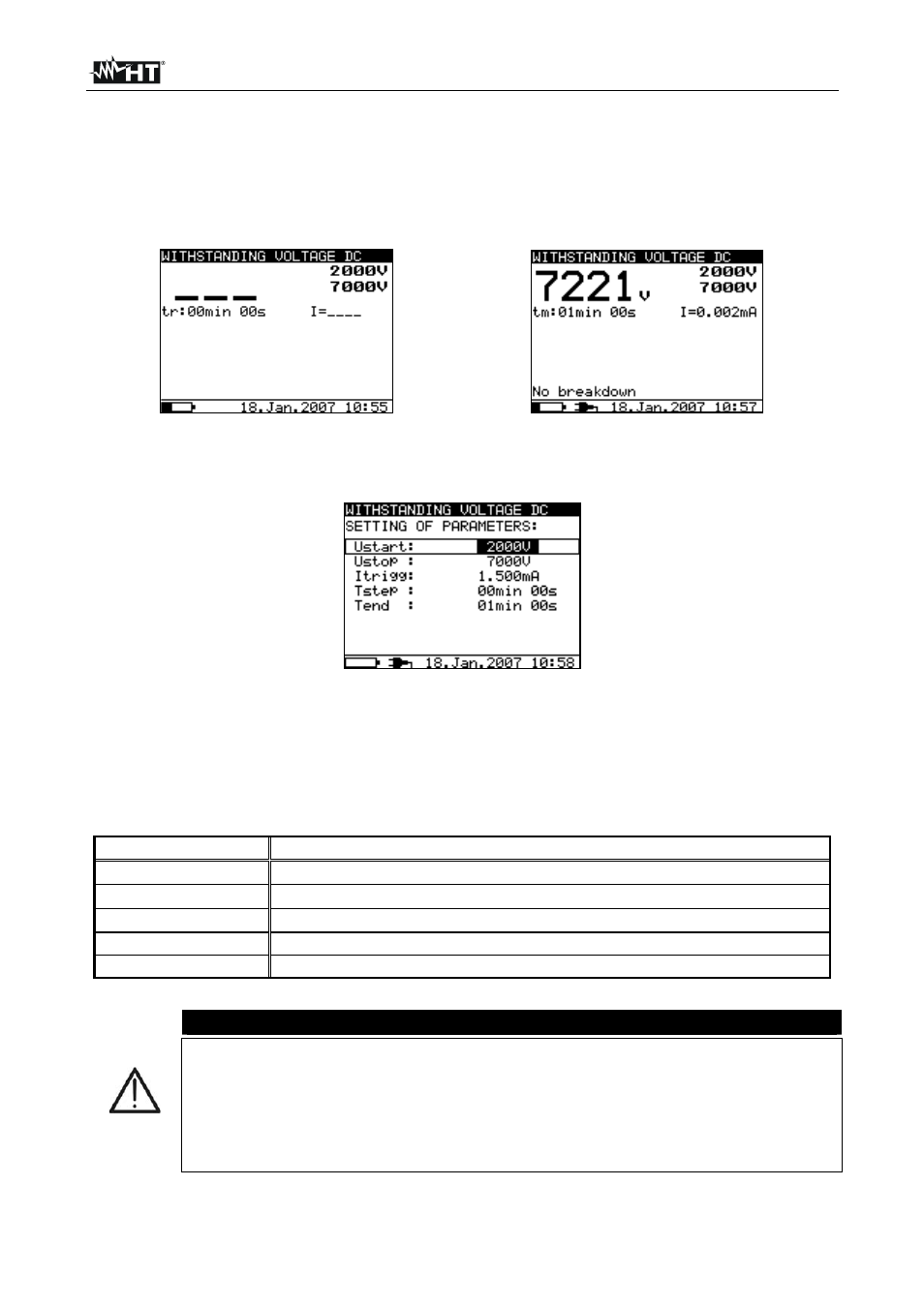
2. Select with arrow keys or the item “WITHSTANDING VOLTAGE DC” on main
menu and confirm with SELECT key. The screen of Fig. 43 is shown by the meter
Fig. 43: Initial screen withstanding test
Fig. 44: Final screen withstanding test
3. Press again the SELECT key to enter in the setup parameters section. The screen of
Fig. 45 is shown by the meter
Fig. 45: Setting parameters
4. Use the arrow keys or for the selection of parameters. The herewith Table 9
shows the meaning of the measurement parameters
5. Set the values by using the arrow keys or . Press SELECT key to select possible
sub-parameters and repeat the settings
6. Press ESC key to save the settings and back to the measurement screen or the
START/STOP key to exit from the settings menu and activate the test
Parameter Description
Ustart
Start test voltage – Range 500V
10kV step 25V
Ustop
Stop test voltage – Range 500V
10kV step 25V
Itrigg
Set trigger leakage current – Range 0.001mA
5mA step 10A
Tstep
Duration of test voltage per one step
Tend
Duration of constant test voltage after reaching stop value
Table 9: Setting of internal parameters
CAUTION
Tstep and Tend are independent timers. The maximum time for each timer
is 30 min 60 s. Tend begins after the completion of the ramp period. Ramp
period can be calculated from:
Ttot-ramp
Tstep * [(Ustop-Ustart) / 25V]
If Tstep is set to 00min 00s, then the ramp voltage increases by
approximately 25 V every 2s