GW Instek GPI-700A Series HSB-001-01/-02 User manual User Manual
Page 8
SCANNER BOX HSB-001-1/2
USER MANUAL
10
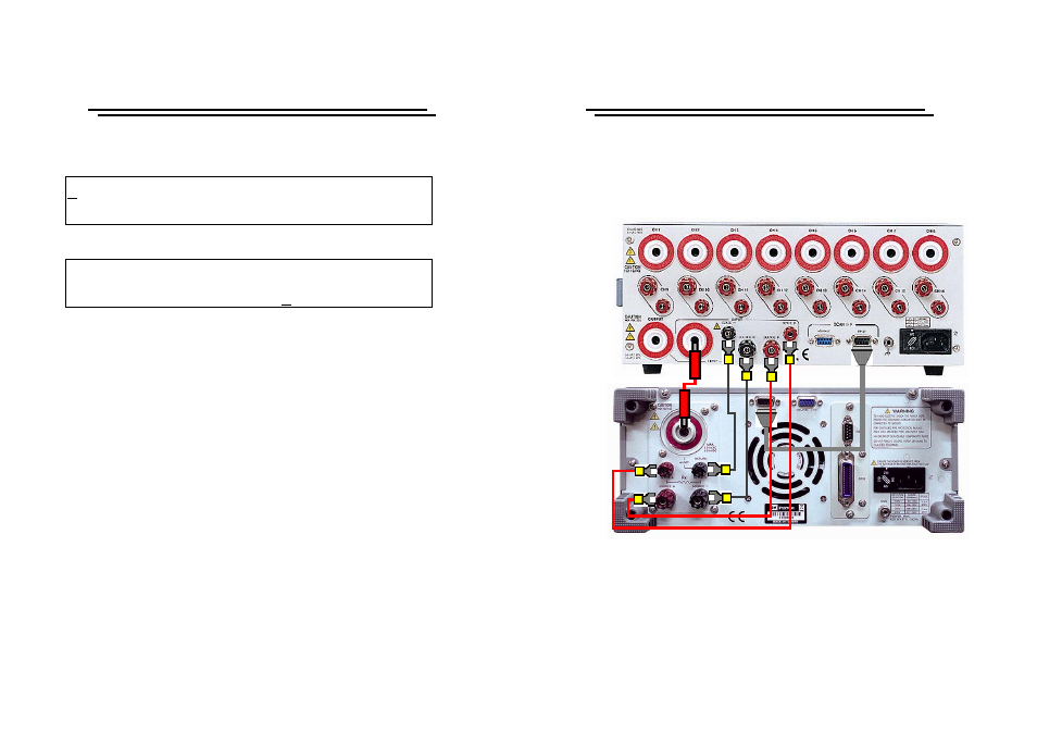
EXAMPLE OF SETTING UP THE HSB-001-1/2
1:01 ACW V = 1.200 kV EDIT
Imax=03.00 mA TEST:060.0S
1:01 ACW V = 1.200 kV EDIT
Channel Hi= 01 Lo=02
When the function jumps from Filed to Channel, select Hi from
01~16 and Lo from 01~16, such as Hi=05 and Lo=01, means a high
voltage will be outputted from the Channel 05, and the channel 01
is a return terminal.
HSB-001-1 : ACW,DCW,IR for Channel 01~08, GB for Channel
09~16
HSB-001-2 : ACW,DCW,IR for Channel 01~16,
If select Channel=00 and Channel=00, there will be no output
from scanner box.
SCANNER BOX HSB-001-1/2
USER MANUAL
11
z
The Configuration
HSB-001-1
HSB-001-1 and GPI-745A
This manual is related to the following products:
See also other documents in the category GW Instek Equipment:
- GDB-03 (99 pages)
- GLA-1000 Series User Manual (111 pages)
- GLA-1000 Series Quick start guide (20 pages)
- GOS-630FC (20 pages)
- GOS-635G (36 pages)
- GOS-6000 Series (27 pages)
- GOS-6103C (30 pages)
- GOS-6100 Series (30 pages)
- GRS-6000A Series (51 pages)
- GDS-122 Installation Guide (4 pages)
- GDS-122 User Manual (52 pages)
- GDS-2000A series CAN/LIN bus User Manual (18 pages)
- GDS-2000A series Quick start guide for DS2-FGN (6 pages)
- GDS-2000A series Freewave User Manual (26 pages)
- GDS-2000A series Quick start guide for Logic analyzer option (18 pages)
- GDS-2000A series Quick start quide for DS2-LAN (2 pages)
- GDS-2000A series Option User Manual (80 pages)
- GDS-2000A series User Manual (261 pages)
- GDS-2000A series Programming Manual (272 pages)
- GDS-2000A series Single sheet for LA Quick start guide (2 pages)
- GBS-1000 Series Programming Manual (88 pages)
- GBS-1000 Series User Manual (187 pages)
- GDS-1000-U Series firmware upgrade (1 page)
- GDS-1000-U Series Programming Manual (70 pages)
- GDS-1000-U Series Quick start guide (2 pages)
- GDS-1000-U Series User Manual (133 pages)
- GDS-1000A-U Series Programming Manual (88 pages)
- GDS-1000A-U Series Quick start guide (2 pages)
- GDS-1000A-U Series User Manual (148 pages)
- GDS-3000 Series GCP-530/1030 current probe User Manual (40 pages)
- GDS-3000 Series GDP-025/050/100 differential probe User Manual (21 pages)
- GDS-3000 Series DS3-PWR Power analysis manual (37 pages)
- GDS-3000 Series User Manual (209 pages)
- GDS-3000 Series Programming Manual (103 pages)
- GDS-3000 Series DS3-SBD Serial Bus decode (29 pages)
- GDS-3000 Series GKT-100 deskew fixture User Manual (1 page)
- GDS-3000 Series GUG-001, GPIB to USB adapter User Manual (15 pages)
- GDS-300 Series User Manual (188 pages)
- GDS-300 Series Programming Manual (139 pages)
- GDS-300 Series Quick start guide (21 pages)
- GRF-3300 Series Student Manual (26 pages)
- GRF-3300 Series Teacher Manual (26 pages)
- GRF-1300A (124 pages)
- GSP-810 User Manual (40 pages)
- GSP-810 Software Manual (3 pages)