GW Instek GPI-700A Series HSB-001-01/-02 User manual User Manual
Page 6
SCANNER BOX HSB-001-1/2
USER MANUAL
6
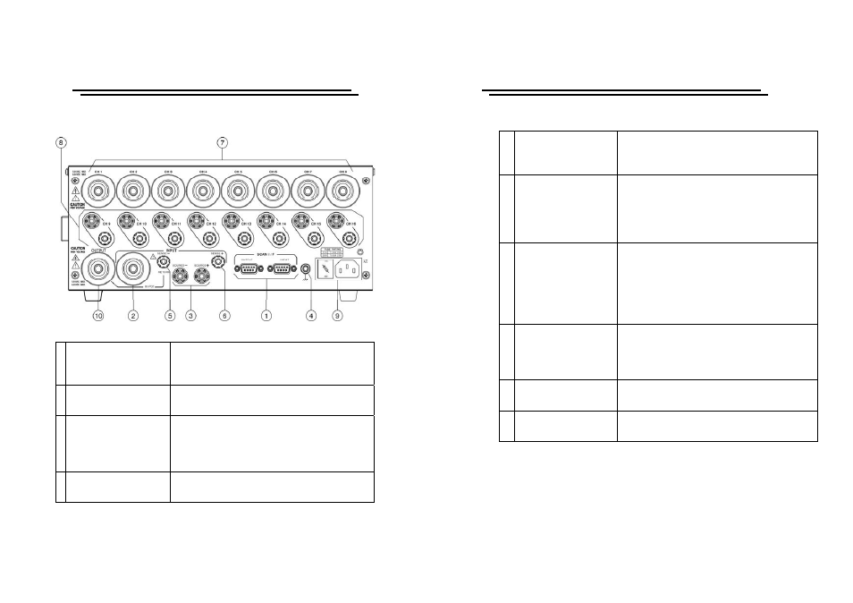
4-2. Rear Panel
1. Control Connect
Interconnect port for connecting the control
cable between the HSB-001-1/2 and the host
instrument.
2. High Voltage Input
Connector is for the high voltage input form
the host instrument.
3. High Current Input
The connector of the high current input for
GPI-745A is used only when the HSB-001-1
is disconnected to the GPT-705A, GPT-715A,
GPI-725A and GPI-735A.
4.
Safety Ground
Connector
Well connect this connector to a ground
system to ensure operation safety.
SCANNER BOX HSB-001-1/2
USER MANUAL
7
5. Return
A connector for interconnecting the return
of the host instrument with the
HSB-001-1/2
6. Ground Bond Return
Common return connector for the Ground
Bond test output. This connector is not used
when HSB-001-1 is connected to the
GPT-705A, GPT-715A, GPI-725A,
GPI-735A.
7. High Voltage Output
Eight individual output ports for high
voltage tests (Dielectric Withstand and
Insulation Resistance tests), The HSB-001-1
is 8 channel high voltage output and The
HSB-001-2 is 16 channel high voltage
outputs.
8.
Ground Bound
Output
Output ports for application of the high
current for Ground Bond tests. The
standard configuration of the HSB-001-1 is
for up to eight Ground Bond outputs.
9.
Fuse Holder with
Voltage Selector
To change AC source voltage, pull the fuse
holder and rotate it to the proper value.
10. High Voltage Output
Connect to the high voltage output of the
next scanner box.