Spi serial bus interface – GW Instek GDS-3000 Series DS3-SBD Serial Bus decode User Manual
Page 26
GDS-3000 Serial Decode User Manual
26
SPI Serial Bus Interface
The serial peripheral interface (SPI) is a full duplex 4 wire
synchronous serial interface. The 4 signals lines: Serial clock line
(SCLK), slave select (SS), Master output/slave input (MOSI, or
SIMO) and the Master input/slave output (MISO, or SOMI). The
word size is configurable from 8, 16 or 32 bits. The SPI triggers on
the data pattern at the start of each framing period. This bus is only
available on 4 channel models.
Panel operation
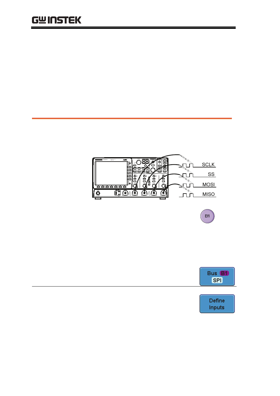
1. Insert each of the bus signals (SCLK, SS, MOSI,
MISO) to one of the oscilloscope channels.
2. Choose Bus 1 or Bus 2 by pressing
the corresponding bus key, B1 or
B2.
Note
The SPI bus decoding function is only available
on 4 channel DSO models.
3. Press Bus from the bottom menu
and choose the SPI serial bus.
Define Inputs
1. Press Define Inputs from the lower
menu.
2. From the side menu choose the
SCLK, SS, MOSI and MISO inputs.
SCLK
CH1~4
SS
CH1~4
- GDB-03 (99 pages)
- GLA-1000 Series User Manual (111 pages)
- GLA-1000 Series Quick start guide (20 pages)
- GOS-630FC (20 pages)
- GOS-635G (36 pages)
- GOS-6000 Series (27 pages)
- GOS-6103C (30 pages)
- GOS-6100 Series (30 pages)
- GRS-6000A Series (51 pages)
- GDS-122 Installation Guide (4 pages)
- GDS-122 User Manual (52 pages)
- GDS-2000A series CAN/LIN bus User Manual (18 pages)
- GDS-2000A series Quick start guide for DS2-FGN (6 pages)
- GDS-2000A series Freewave User Manual (26 pages)
- GDS-2000A series Quick start guide for Logic analyzer option (18 pages)
- GDS-2000A series Quick start quide for DS2-LAN (2 pages)
- GDS-2000A series Option User Manual (80 pages)
- GDS-2000A series User Manual (261 pages)
- GDS-2000A series Programming Manual (272 pages)
- GDS-2000A series Single sheet for LA Quick start guide (2 pages)
- GBS-1000 Series Programming Manual (88 pages)
- GBS-1000 Series User Manual (187 pages)
- GDS-1000-U Series firmware upgrade (1 page)
- GDS-1000-U Series Programming Manual (70 pages)
- GDS-1000-U Series Quick start guide (2 pages)
- GDS-1000-U Series User Manual (133 pages)
- GDS-1000A-U Series Programming Manual (88 pages)
- GDS-1000A-U Series Quick start guide (2 pages)
- GDS-1000A-U Series User Manual (148 pages)
- GDS-3000 Series GCP-530/1030 current probe User Manual (40 pages)
- GDS-3000 Series GDP-025/050/100 differential probe User Manual (21 pages)
- GDS-3000 Series DS3-PWR Power analysis manual (37 pages)
- GDS-3000 Series User Manual (209 pages)
- GDS-3000 Series Programming Manual (103 pages)
- GDS-3000 Series GKT-100 deskew fixture User Manual (1 page)
- GDS-3000 Series GUG-001, GPIB to USB adapter User Manual (15 pages)
- GDS-300 Series User Manual (188 pages)
- GDS-300 Series Programming Manual (139 pages)
- GDS-300 Series Quick start guide (21 pages)
- GRF-3300 Series Student Manual (26 pages)
- GRF-3300 Series Teacher Manual (26 pages)
- GRF-1300A (124 pages)
- GSP-810 User Manual (40 pages)
- GSP-810 Software Manual (3 pages)