Bus trigger settings – GW Instek GDS-3000 Series DS3-SBD Serial Bus decode User Manual
Page 16
GDS-3000 Serial Decode User Manual
16
Bus Trigger Settings
The bus trigger conditions should be set at any time after UART,
I
2
C or SPI have been selected as the B1 or B2 buses. If the trigger is
not set to Bus the trigger will not be stable.
Panel Operation
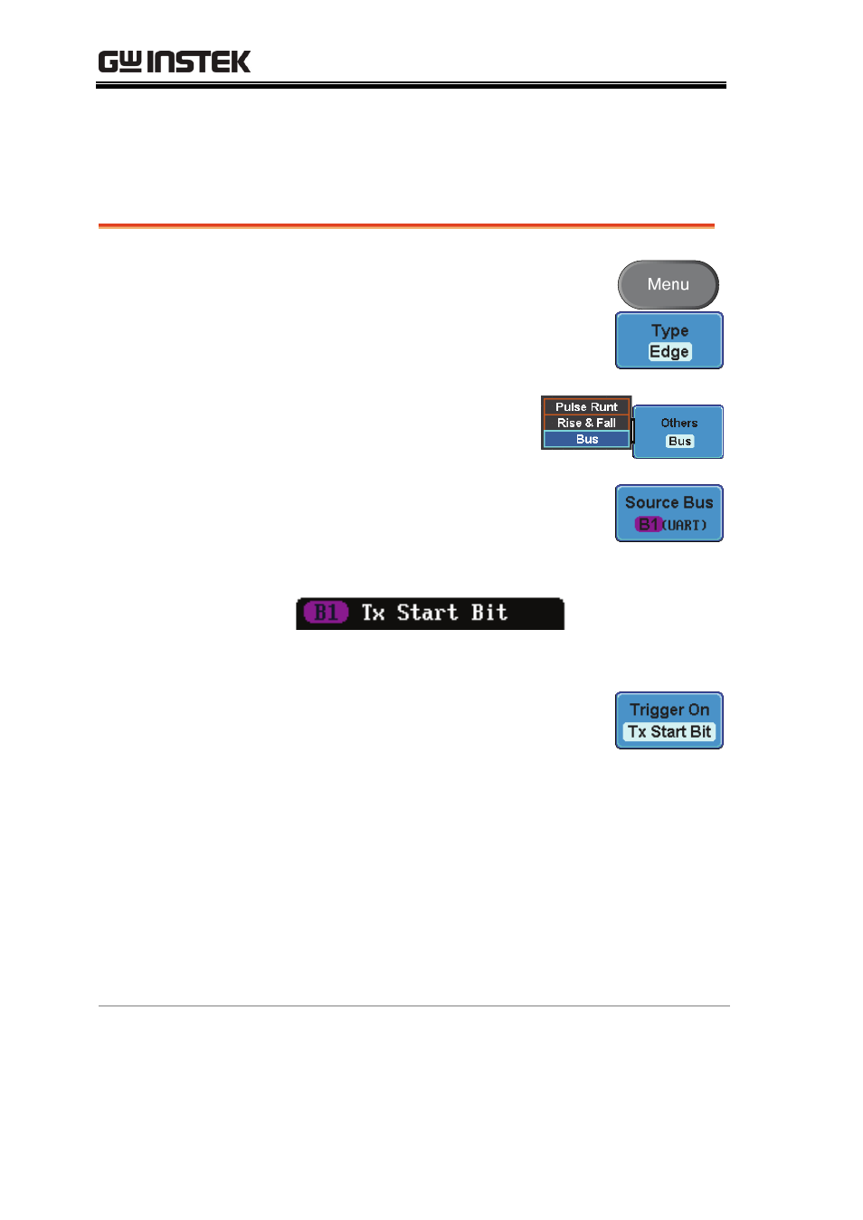
1. Press the trigger Menu key and
press Type from the bottom menu.
2. Press Others from the side
menu and select Bus.
3. Press Source Bus from the bottom
menu and select the source bus, B1
or B2. The B1/B2 trigger appear at
the bottom of the display.
From left: Bus, Trigger On.
4. Press Trigger On and select the
triggering condition for the
selected bus.
UART
Tx Start Bit, Rx Start Bit, Tx End of
Packet, Rx End of Packet, Tx Data,
Rx Data, Tx Parity Error, Rx Parity
Error
I
2
C
Start, Repeat Start, Stop, Missing
Ack, Address, Data, Address/Data
SPI
SS Active, MOSI, MISO,
MOSI&MISO
Trigger On - Data
If Data was configured for the Trigger On
setting, then the number of bytes, data and
addressing mode (I
2
C) can be configured.
- GDB-03 (99 pages)
- GLA-1000 Series User Manual (111 pages)
- GLA-1000 Series Quick start guide (20 pages)
- GOS-630FC (20 pages)
- GOS-635G (36 pages)
- GOS-6000 Series (27 pages)
- GOS-6103C (30 pages)
- GOS-6100 Series (30 pages)
- GRS-6000A Series (51 pages)
- GDS-122 Installation Guide (4 pages)
- GDS-122 User Manual (52 pages)
- GDS-2000A series CAN/LIN bus User Manual (18 pages)
- GDS-2000A series Quick start guide for DS2-FGN (6 pages)
- GDS-2000A series Freewave User Manual (26 pages)
- GDS-2000A series Quick start guide for Logic analyzer option (18 pages)
- GDS-2000A series Quick start quide for DS2-LAN (2 pages)
- GDS-2000A series Option User Manual (80 pages)
- GDS-2000A series User Manual (261 pages)
- GDS-2000A series Programming Manual (272 pages)
- GDS-2000A series Single sheet for LA Quick start guide (2 pages)
- GBS-1000 Series Programming Manual (88 pages)
- GBS-1000 Series User Manual (187 pages)
- GDS-1000-U Series firmware upgrade (1 page)
- GDS-1000-U Series Programming Manual (70 pages)
- GDS-1000-U Series Quick start guide (2 pages)
- GDS-1000-U Series User Manual (133 pages)
- GDS-1000A-U Series Programming Manual (88 pages)
- GDS-1000A-U Series Quick start guide (2 pages)
- GDS-1000A-U Series User Manual (148 pages)
- GDS-3000 Series GCP-530/1030 current probe User Manual (40 pages)
- GDS-3000 Series GDP-025/050/100 differential probe User Manual (21 pages)
- GDS-3000 Series DS3-PWR Power analysis manual (37 pages)
- GDS-3000 Series User Manual (209 pages)
- GDS-3000 Series Programming Manual (103 pages)
- GDS-3000 Series GKT-100 deskew fixture User Manual (1 page)
- GDS-3000 Series GUG-001, GPIB to USB adapter User Manual (15 pages)
- GDS-300 Series User Manual (188 pages)
- GDS-300 Series Programming Manual (139 pages)
- GDS-300 Series Quick start guide (21 pages)
- GRF-3300 Series Student Manual (26 pages)
- GRF-3300 Series Teacher Manual (26 pages)
- GRF-1300A (124 pages)
- GSP-810 User Manual (40 pages)
- GSP-810 Software Manual (3 pages)