Alarm and trouble activation, Facp activations appendix a: ms-5210ud – Fire-Lite ACM-8RF Control Relay Module User Manual
Page 23
FACP Activations
Appendix A: MS-5210UD
ACM-8RF PN 50362:C 03/21/01
23
Alarm and Trouble Activation
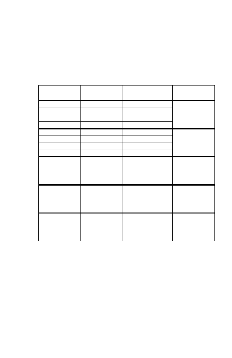
Table 5 provides the switch settings for ACM-8RF DIP switch SW3 when
configuring the relays to trigger for alarm and trouble activation. Note that a
maximum of five ACM-8RFs are required if relays are to be designated to
trigger on any FACP status change. If system status relays are not required,
three ACM-8RFs may be used to allow individual relay triggering for alarm
and trouble activation of FACP zones 1 through 10. When using only three
ACM-8RFs, be sure to use the switch settings for the 3rd, 4th and 5th
ACM-8RF in Table 5.
Table 5 SW3 Settings for Alarm and Trouble
MS-5210UD
Zone
ACM-8RF
Alarm Relay
ACM-8RF Trouble
Relay
SW3 Settings
System Status
1=System Alarm
5=System Trouble
1st ACM-8RF
SW3-1 = ON
SW3-5 = ON
All others = OFF
System Status
Relay 2 (not used)
Relay 6 (not used)
System Status
Relay 3 (not used)
7=System Off Normal
System Status
Relay 4 (not used)
8=System Supervisory
System Status
Relay 1 (not used)
5=NAC(s) Fault
2nd ACM-8RF
SW3-2 = ON
SW3-5 = ON
All others = OFF
System Status
Relay 2 (not used)
6=Walktest Start
System Status
Relay 3 (not used)
7=Battery Fail
System Status
Relay 4 (not used)
8=AC Fail
Z1
Relay 1
Relay 5
3rd ACM-8RF
SW3-3 = ON
SW3-5 = ON
All others = OFF
Z2
Relay 2
Relay 6
Z3
Relay 3
Relay 7
Z4
Relay 4
Relay 8
Z5
Relay 1
Relay 5
4th ACM-8RF
SW3-4 = ON
SW3-5 = ON
All others = OFF
Z6
Relay 2
Relay 6
Z7
Relay 3
Relay 7
Z8
Relay 4
Relay 8
Z9
Relay 1
Relay 5
5th ACM-8RF
SW3-1 = ON
SW3-6 = ON
All others = OFF
Z10
Relay 2
Relay 6
n/a
Relay 3 (not used)
Relay 7 (not used)
n/a
Relay 4 (not used)
Relay 8 (not used)