Edwards Signaling 439DEX User Manual
Description, Installation
© 2011 UTC Fire & Security. All rights reserved.
1 / 4
P/N P-047550-0587 • REV 6.0 • ISS 04NOV11
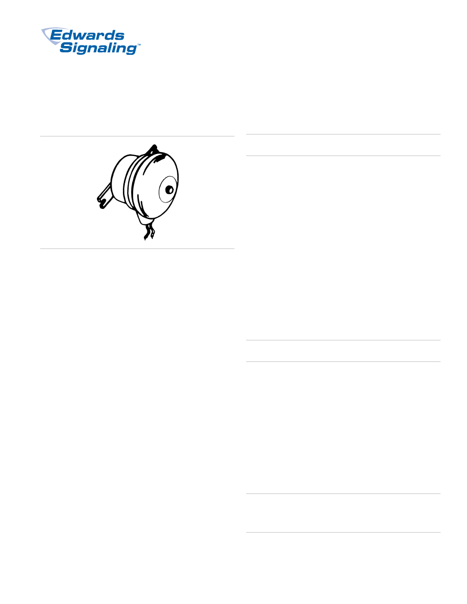
438DEX and 439DEX Fire Alarm Bells
Installation Sheet
Description
Edwards' catalog series 438DEX and 439DEX fire alarm bells
are heavy duty, diode polarized, vibrating bells intended for
use in compatible fire alarm systems and other applications
requiring electrical supervision of signaling circuit field wiring.
The 438DEX series of bells are AC-powered and the 439DEX
are DC-powered. The bells are electro-mechanical devices and
utilize solid state components. These appliances must be
installed in accordance with the applicable requirements in the
latest editions of the NFPA codes and standards, and the local
authority having jurisdiction.
Both series of the bells are listed for installation in the following
hazardous locations: Class I, Divisions 1 and 2, Groups B, C
and D, Class I, Zones 1 and 2, Groups IIA and IIB, Class II,
Divisions 1 and 2, Groups E, F and G and Class III, Zones 1
and 2.
Installation
The following items (not supplied) are required for installation
of the bell:
•
3/4 in. National Pipe Taper (NPT) conduit to contain
signaling circuit wires.
•
One 3/4 in.-14 NPT nipple
•
One conduit outlet box suitable for use in the hazard
•
Two fasteners up to 3/8 in. diameter and washers suitable
for securing bell to mounting surface
• Four
wire
nuts
Caution:
Do not apply power to the bell until installation has
been completed and the cover has been secured on outlet box.
The bell can be mounted to any solid surface.
To install the bell:
1. Refer to Figure 1 on page 2. Remove the gong support
bolt, remove the gong and set it aside. Bring the bell wires
through the nipple and secure the nipple onto the bell
(being careful not to twist or crimp the wires). Feed the bell
wires into the outlet box and secure the outlet box onto the
nipple (again being careful of the wires). Secure the 3/4 in.
NPT conduit onto the outlet box.
2. Place the bell against mounting surface and mark
mounting hole positions, the dimensions are shown in
Figure 2. Install fasteners with washers through mounting
brackets and secure bell to surface.
3. Replace the gong in its original orientation and secure.
4. Remove the cover from the conduit outlet box. Feed the
signaling circuit field wires through the conduit and into
and out of the outlet box along with the four bell wires.
Caution:
Wire run must be broken to provide electrical
supervision.
5. Connect the signaling circuit wires to the bell wires per the
applicable wiring diagram. For 438DEX series AC bells,
see Figure 3. For 439DEX series DC bells, see Figure 4.
Make wire connections using wire nuts. Also, refer to the
applicable installation instructions for wiring connections
used in the fire alarm control panel for additional wiring
connection details. Connect only two wires per wire nut at
each connection. Do not twist wires together.
6. Replace the cover on outlet box.
7. Apply power to the fire alarm control panel. Initiate an
alarm to activate the bell and verify that it sounds. Then
reset the panel to silence the bell and return to the
supervisory mode.
WARNING:
This device will not operate without electrical
power. As fires frequently cause power interruptions, we
suggest you discuss further safeguards with your local fire
protection specialist.