Wire routing, Wiring diagrams – Edwards Signaling FireShield Single-Zone Panel User Manual
Page 3
Installation Sheet
04MAR03
P/N: 3100589 REV: 1.0
FireShield Single-Zone Panel - Installation and Operating Instructions
3 / 6
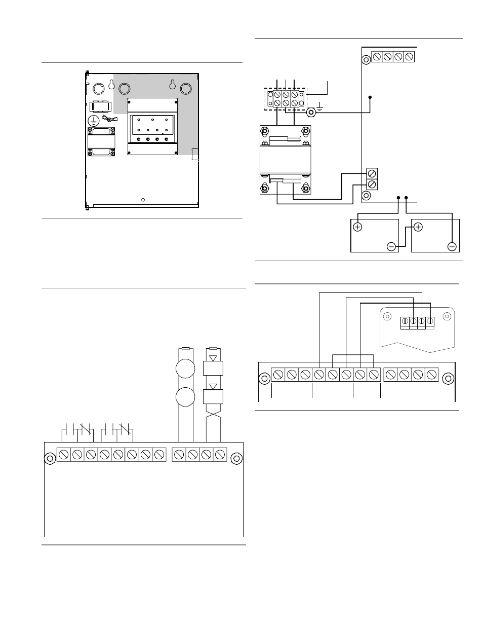
Wire routing
All wiring is power-limited except for AC power and battery
wiring. All wiring is supervised unless noted otherwise.
Keep power-limited wiring in the shaded
area and nonpower-limited wiring in the
unshaded area at all times.
Wiring diagrams
The following diagrams show field wiring, AC power and
battery wiring, and RTU wiring.
Field wiring
AUX PW
R –
AU
X PW
R +
C
o
m
m
on
t
ro
ubl
e
re
la
y
1
A
@
3
0
Vd
c,
r
es
ist
iv
e
N
ons
upe
rv
is
ed
[7
][9
]
C
o
m
m
o
n
al
ar
m
r
el
ay
1
A
@
30
Vd
c,
r
esi
st
iv
e
N
o
ns
up
er
vi
se
d
[7
][
9]
AUX
PW
R
o
ut
p
ut
24
V
dc,
nom
in
al
@
0
.1
A
EOLR
+
IDC–
IDC+
−
+
−
+
NAC–
NAC+
−
+
−
EOLR
NOTIFICATION APPLIANCE CIRCUITS [2] [3] [4] [8]
Class B (Style Y)
Operating voltage: 24 Vfwr
Operating current: 1.0 A
EOLR:
Circuit impedance: 13 , 50.0 F, max
4.7 k , 1/2 W (P/N EOL4.7)
Ω
µ
Ω
INITIATING DEVICE CIRCUITS [2] [3] [6] [8]
Class B (Style B)
Operating voltage: 16.7 to 26.4 Vdc
Operating current: 3.0 mA
Circuit impedance: 13 , 50.0 F, max
EOLR: 4.7 k , 1/2 W (P/N EOL4.7)
Ω
µ
Ω
AC power and battery wiring
24 Vac
IN
Main supply circuit
120 V, 60 Hz, 0.36 A
from dedicated branch
supply
EGND
Li
n
e
Ea
rt
h G
N
D
Ne
u
tr
a
l
Red
Black
Rechargeable battery circuit
Voltage: 24 Vdc
Amp-hour capacity: 4.5 Ah max.
sealed lead acid batteries only
12 Vdc
Battery
12 Vdc
Battery
Note: Make sure to
reattach the AC
terminal cover when
power wiring is
complete.
RTU wiring
Jumper wire
TB1
+
+
NC NO
RTU
[9]
NO
ALARM
NC
NO
NC
–
+
AUX PWR
TROUBLE
Notes
The following notes match the wiring label notes inside the panel,
and are not numbered sequentially.
[2] Class B wiring only
[3] Listed EOLRs must be installed as shown for proper
supervision
[4] Marking indicates output signal polarity when the circuit is
active. Polarity reverses when the circuit is not active. Wire
notification appliances accordingly. Notification appliance
polarity shown in active state.
[6] When the IDC is programmed for alarm verification, both
automatic and manually activated alarm initiating devices can
be connected simultaneously. Manually initiated devices will
not be verified (delayed).
[7] Relay circuits can only be connected to power-limited sources
[8] Installation limits under jurisdiction of local authority
[9] Contacts shown in normal condition