110 cd model, Electronic strobes, Figure 3. v/i curves – Edwards Signaling CS405 User Manual
Page 2: 15/75 cd model
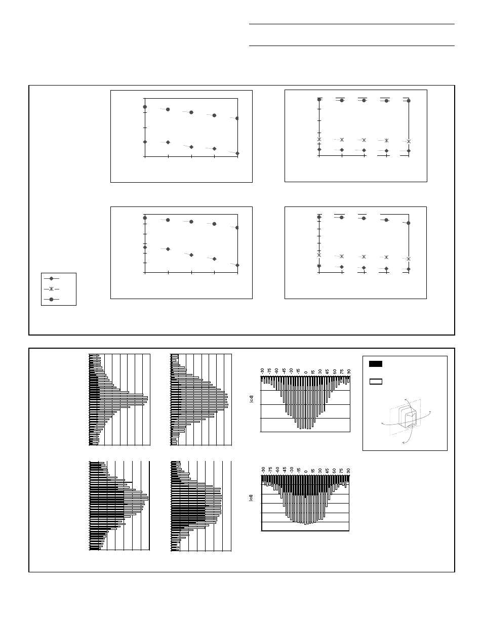
Figure 3. V/I Curves
110 cd Model
NOTE:
Use the average current rating to establish the maximum number of strobes, wire gauge and standby power requirements. Consult the
manufacturer to determine the peak current effects on the system.
910
900
890
870
828
220
210
200
190
235
370
363
357
330
385
150
250
350
450
550
650
750
850
950
20
21
22
23
24
Operating Voltage Full Wave Rectified
Operating Current (mA)
265
219
235
245
260
340
315
325
330
335
200
225
250
275
300
325
350
20
21
22
23
24
Operating Voltage DC
Operating Current (mA)
Iavg
Irms
Ipeak
Peak Inrush Current @ 24 Vdc = 7.8 A for
less than 50 microseconds.
Peak Inrush Current @ 24 Vdc = 6.8 A for
less than 50 microseconds.
GENERAL SIGNAL BUILDING SYSTEMS CORPORATION
SARASOTA , FL 941-739-4300 Fax. 941-753-1806
CHESHIRE, CT 203-699-3000 Fax. 203-699-3075
Figure 4. Strobe Light Output Distribution Patterns
UL Minimum
Requirement
Typical Output
90
O
90
O
-90
O
HORIZONTAL
VERTICAL
-90
O
0
25
50
75
100
125
150
175
- 90
- 75
- 60
- 45
- 30
- 15
0
15
30
45
60
75
90
Θ
(c d)
0
25
50
75
100
125
150
175
-90
-75
-60
-45
-30
-15
0
15
30
45
60
75
90
Θ
(c d)
0
25
50
75
100
125
150
Θ
110 cd
Model
Horizontal
Ceiling
Vertical
NOTE:
This equipment has been tested and found to comply with the limits for a
Class A digital device, pursuant to Part 15 of the FCC Rules. These limits are
designed to provide reasonable protection against harmful interference when the
equipment is operated in a commercial environment. This equipment generates,
uses and can radiate radio frequency energy and, if not installed and used in
accordance with the instruction manual, may cause harmful interference to radio
communications. Operation of this equipment in a residential area is likely to cause
harmful interference in which case the user will be required to correct the
interference at his own expense.
CAUTION:
Changes or modifications to this equipment not expressly approved by
the party responsible for compliance could void the user’s authority to operate the
equipment.
Electronic strobes
CS405-7A-T
Electronic strobe, 15/75 cd red
CS405-8A-T
Electronic strobe, 110 cd red
530
526
524
522
520
98
94
92
90
102
186
181
177
172
190
50
150
250
350
450
550
20
21
22
23
24
Operating Voltage Full Wave Rectified
Operating Current (mA)
125
105
113
116
124
185
165
170
175
180
100
125
150
175
200
20
21
22
23
24
Operating Voltage DC
Operating Current (mA)
15/75 cd Model
Peak Inrush Current @ 24 Vdc = 7.6 A for
less than 50 microseconds.
Peak Inrush Current @ 24 Vdc = 6.8 A for
less than 50 microseconds.
0
20
40
60
80
Θ
15/75 cd
Model
0
10
20
30
40
50
60
70
80
-90
-75
-60
-45
-30
-15
0
15
30
45
60
75
90
Θ
(c d)
0
10
20
30
40
50
60
70
80
-90
-75
-60
-45
-30
-15
0
15
30
45
60
75
90
Θ
(c d)
P/N 387627 © 1996
OWEN SOUND, CANADA 519-376-2430 Fax. 519-376-7258
INTERNATIONAL: CANADA 905-270-1711 Fax. 905-270-9553