Edwards Signaling 52 User Manual
Warnings, Signals
P-047550-0541 ISSUE 13 © 2003
Installation Instructions for Catalog Series 49, 50, 50SIN,
51 and 52 AdaptaBeacon
®
Signals
Description
Description
Description
Description
Description
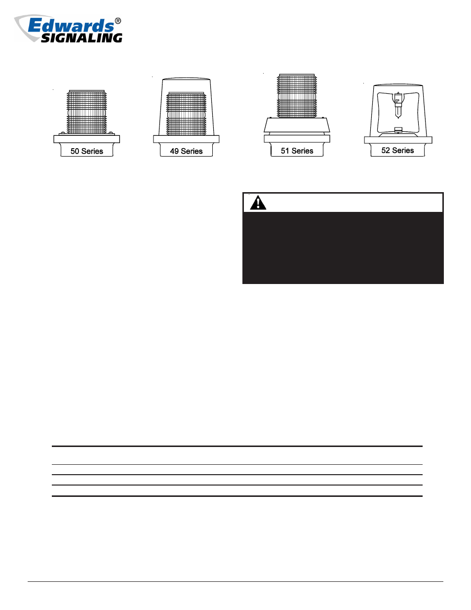
Catalog Series 49, 50, 50SIN, 51 and 52 AdaptaBeacon sig-
nals are UL and cUL listed, general purpose visual and
visual/audible signaling appliances. The 49 and 50 series
are flashing lights. The 50SIN is a steady-on light. The 51
series are combination flashing lights with horn. The 51
series come in single and double horn versions; the double
horn version is denoted by a 2H in its catalog number.
The 52 series are rotating lights.
The 49, 50, 50SIN, 51 and 52 series signals are suitable for
indoor or outdoor (weatherproof) installation and uti-
lize a standard base that allows direct surface mounting,
mounting on a 4" (102 mm) octagon box, or mounting
on 1/2" (13 mm) NPT conduit. For outdoor installation,
the signals must be mounted on conduit.
For product specification details see Table 2. Refer to
Table 3 for available replacement lamps, flashers, domes
and lenses.
PLC Compatibility
The electrical input load requirements for PLC compat-
ible signaling devices are listed in Table 1. Signaling
devices may be directly connected to output cards that
meet these input load requirements.
Installation
Installation
Installation
Installation
Installation
WARNINGS
To prevent electrical shock, ensure that power is
disconnected before installing the signal.
To prevent electrical shock, use care when
disassembling the signal to prevent tearing of the
permanently affixed gaskets provided for
weatherproofing.
Install in accordance with the latest edition of the Na-
tional Electrical Code and local regulations.
1.
For the 49, 50, 50SIN, 51 and 52 series signals, remove
the base from the signal using one of the following
applicable procedures.
49 Series: See Figure 1. Remove the screw in the
clamp ring, remove the ring, and lift off the dome.
Loosen the three screws in the base of the lens and
turn the lens clockwise to remove. Then remove the
two screws that are partially set into the raised area
of the lamp assembly mounting plate, lift the
assembly off of the base, and pull the wire leads out
of the conduit entrance hole in the base. Proceed to
step 2 for installation of the base.
Table 1. PLC Compatibility
Operating
Maximum off state
Continuous on
Surge (inrush/duration)
Cat. No.
voltage*
leakage current (mA)
current (mA)
(A/ms**)
50( )-N5-40WH
120V AC
25
300
2/8
50SIN( )-N5-40WH
120V AC
25
290
0.47/8
51( )-N5-40W
120V AC
25
350
2/8
*All AC volts at 60 Hz
**Amps/milliseconds
Cheshire, CT 06410 203-699-3300 (Ph)
203-699-3365 (Cust. Serv. Fax)
203-699-3078 (Tech. Serv. Fax)