Ordering/electrical specifications, General specifications, Mounting configurations – Edwards Signaling 166 Series User Manual
Page 2
Ordering/Electrical Specifications
PART NUMBER
CONTACT
1
LOAD RATING
SWITCHING VOLTAGE
SWITCHING CURRENT
VOLTAGE
SENSE RANGE
2
BREAK RANGE
LEAD LENGTH
CONFIG.
(DC)
MAXIMUM (DC)
MAXIMUM (DC)
DROP
NOMINAL
NOMINAL
NOMINAL
166-RM-01K
N.C.
100W
5.0A@20V
1.5V
1.6"(4.0cm)
2.1"(5.3cm)
1'(0.3m)
166-RM-06K
N.C.
100W
5.0A@20V
1.5V
1.6"(4.0cm)
2.1"(5.3cm)
6'(1.8m)
166-RM-08K
N.C.
100W
5.0A@20V
1.5V
1.6"(4.0cm)
2.1"(5.3cm)
8'(2.4m)
166-RM-12K
N.C.
100W
5.0A@20V
1.5V
1.6"(4.0cm)
2.1"(5.3cm)
12'(3.6m)
166-RP-06K
N.C.
100W
5.0A@20V
1.5V
1.9"(4.8cm)
2.4"(6.1cm)
6'(1.8m)
166-RP-12K
N.C.
100W
5.0A@20V
1.5V
1.9"(4.8cm)
2.4"(6.1cm)
12'(3.6m)
166-RN-01K
N.C.
100W
5.0A@20V
1.5V
Switch Only
Switch Only
1'(0.3m)
166-RN-06K
N.C.
100W
5.0A@20V
1.5V
Switch Only
Switch Only
6'(1.8m)
166-SN-06K
N.O.
100W
5.0A@20V
1.5V
Switch Only
Switch Only
6'(1.8m)
166-P
Actuator P Only
150-Z
Actuator M Only
Warning— Each electrical rating is an individual maximum and cannot be exceeded!
Note: This switch cannot be used for AC applications. In DC applications it is polarity sensitive white to positive, black to negative.
1
Configuration with actuator away from the switch
2
Proximity of ferrous materials usually reduces sense range — typically by 50%. The shape and type of material cause a wide diversity of effects.
Testing is required to determine actual sense range for specific applications.
General Specifications
Enclosure
Epoxy-coated aluminum
Temperature Range
-40
°
F to 180
°
F (-40
°
C to 80
°
C)
Environmental
Hermetically Sealed Contact Switch
Sealed in Polyurethane
NEMA Rating
1, 2, 3, 4, 4X, 5, 6, 12
Protection Class
IP 67
Response Time
1 msec
Life Cycles
100,000 Under Full Load;
Up to 200,000,000 Under Dry Circuit
Lead Types/O.D.
18/2 SJTOW (K)/0.30" (0.76cm)
UL/CSA
All Models
File E 122942
LR89176
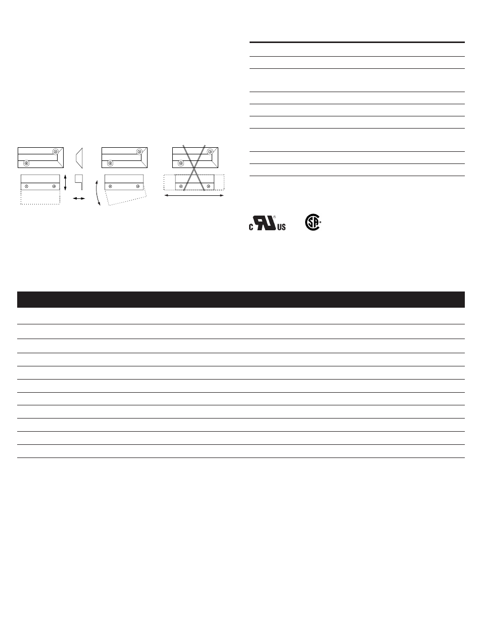
Parallel Actuation
Not Recommended
Perpendicular
Actuation
Door
Actuation
Pivot Actuation
Best
Best
Figure 2
Good
Mounting Configurations
Three configurations are appropriate for interlock applications. The parallel
actuation can result in on/off/on signal if the actuator passes by the switch rather
than coming to rest in proximity to it. This is NOT a recommended configuration for
interlock applications.
• Do not mount for parallel actuation. An on-off-on signal may result when the
actuator passes by the switch.
2. Mount the switch on the stationary frame of the machine and connect the electrical
wiring. When mounting the switch on an ungrounded machine, connect the ground
lead to one of the mounting screws.
3. Mount the actuator on the movable guard, door, or gate.