General specifications, Ordering/electrical specifications, Wire color code – Edwards Signaling 114 User Manual
Page 2
General Specifications
Enclosure
ABS Plastic
Temperature Range
-40
°
F to 180
°
F (-40
°
C to 80
°
C)
Environmental
Hermetically Sealed Contact Switch
Sealed in Polyurethane
NEMA Rating
1, 2, 3, 4, 4X, 5, 6, 12
Protection Class
IP 67
Response Time
1 msec, 10 msec (150VA)
Life Cycles
100,000 Under Full Load;
Up to 200,000,000 Under Dry Circuit
Lead Types/O.D.
18/2 SJTOW (K)/0.30" (0.76cm)
18/3 SJTOW (K)/0.33" (0.84cm)
18/2 or 18/3 Jacketed (J)/O.24" (0.62cm)
18-2 Flying Lead (V) AWG/0.05" (0.13cm)
22/2 Jacketed (J)/0.16" (0.41cm)
UL/CSA
All Models
Ordering/Electrical Specifications
PART NUMBER
CONTACT
1
LOAD RATING
SWITCHING VOLTAGE
SWITCHING CURRENT
CONTACT
SENSE RANGE
2
BREAK RANGE
LEAD LENGTH
CONFIG.
AC/DC
MAXIMUM, AC/DC
MAXIMUM, AC/DC
RESISTANCE
NOMINAL
NOMINAL
NOMINAL
114-1N-08(J)
N.O.
15VA/15W
0.5A@30V
0.5A@30V
Switch Only
Switch Only
8'(2.4m)
114-3Y-12(K)
N.C.
100VA/84W
3
3.0A
3
@34V
3.0A
3
@28V
1.0 Ohms
0.7"(1.8cm)
1.2"(3.0cm)
12'(3.6m)
114-4Y-06(K)
SPDT
100VA/84W
3
3.0A
3
@34V
3.0A
3
@28V
1.0 Ohms
0.7"(1.8cm)
1.2"(3.0cm)
6'(1.8m)
114-6N-06(K)
N.O.
25VA/25W
0.7A@35V
1.0A@25V
1.0 Ohms
Switch Only
Switch Only
6"(1.8m)
114-6Y-06(K)(J)
N.O.
25VA/25W
0.7A@35V
1.0A@25V
0.2 Ohms
1.0" (2.5cm)
2.0"(5.1cm)
6'(1.8m)
114-6Y-12(K)
N.O.
25VA/25W
0.7A@35V
1.0A@25V
0.2 Ohms
1.0"(2.5cm)
2.0"(5.1cm)
12'(3.6m)
114-7Y-06(K)
N.O.
100VA/84W
3
3.0A
3
@34V
3.0A
3
@28V
1.0 Ohms
0.7"(1.8cm)
1.2"(3.0cm)
6'(1.8m)
114-7Y-12(K)
N.O.
100VA/84W
3
3.0A
3
@34V
3.0A
3
@28V
1.0 Ohms
0.7"(1.8cm)
1.2"(3.0cm)
12'(3.6m)
114-8Y-06(K)
5
N.O./
150VA/NA
NA
1.25A@120V
4
NA
NA
1.0"(2.5cm)
1.5"(3.8cm)
6'(1.8m)
114-8Y-12(K)
5
N.O./
150VA/NA
NA
1.25A@120V
4
NA
NA
1.0"(2.5cm)
1.5"(3.8cm)
12'(3.6m)
114-8Y-06(K)-SER25
5
N.O./
150VA/NA
NA
1.25A@120V
4
NA
NA
1.0"(2.5cm)
1.5"(3.8cm)
6'(1.8m)
114-17N-06(V)
N.O.
100VA/100W
3.0A@35V
Switch Only
Switch Only
6'(1.8m)
114-Y
Actuator Only
Included with all switches unless otherwise noted.
Warning— Each electrical rating is an individual maximum and cannot be exceeded!
1
Configuration with actuator away from the switch
2
Proximity of ferrous materials usually reduces sense range — typically by 50%. The shape and type of material cause a wide diversity of effects.
Testing is required to determine actual sense range for specific applications.
3
Rated at 3.0A for 6,000 cycles only. Other ratings are at 100,000 cycles.
4
Can withstand inrush surge up to 4 amps. Voltage Drop 1.5V. Minimum switch current 30mA.
5
Maximum 10 switches in series; SER25 – Maximum 25 switches in series.
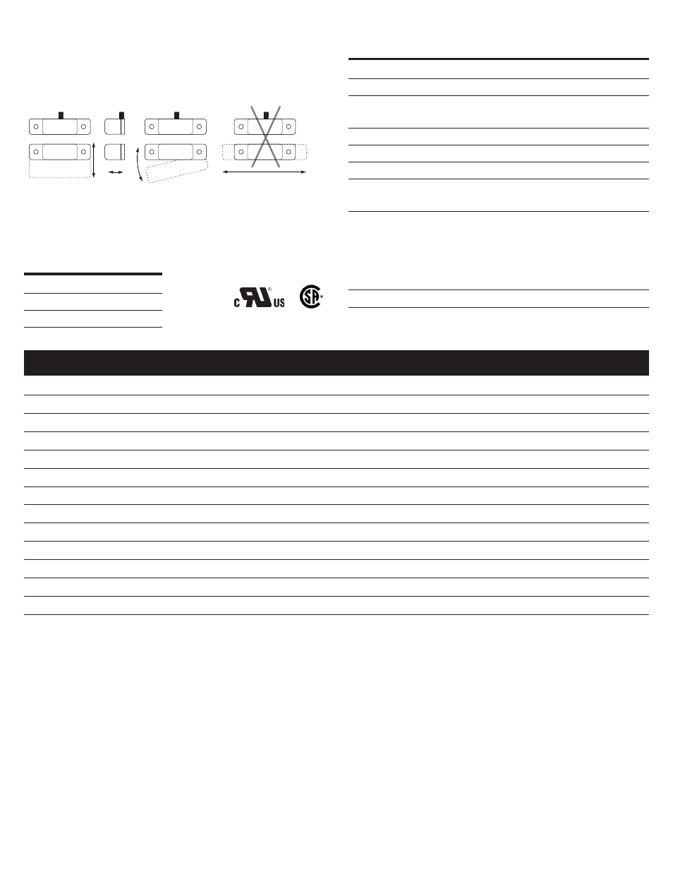
The interlock switch and actuator magnet should be mounted in only three
configurations for actuation:
Three configurations are appropriate for interlock applications. The parallel actuation
can result in on/off/on signal if the actuator passes by the switch rather than
coming to rest in proximity to it. This is NOT a recommended configuration for
interlock applications.
File E 122942
Parallel Actuation
Not Recommended
Perpendicular
Actuation
Door
Actuation
Pivot Actuation
Best
Best
Figure 2
Good
LR89176
triac
output
triac
output
triac
output
Wire Color Code
Black
COM
White
N.O.
Red
N.C.
P/N 12520 • REV D • REB 19FEB13