Warning, Maintenance – Edwards Signaling 107DDV2-G1 User Manual
Page 2
P/N 3100106 ISSUE 2
Figure 2. Detail of Bracket Mounting
Figure 3. Detail of Ceiling Mounting
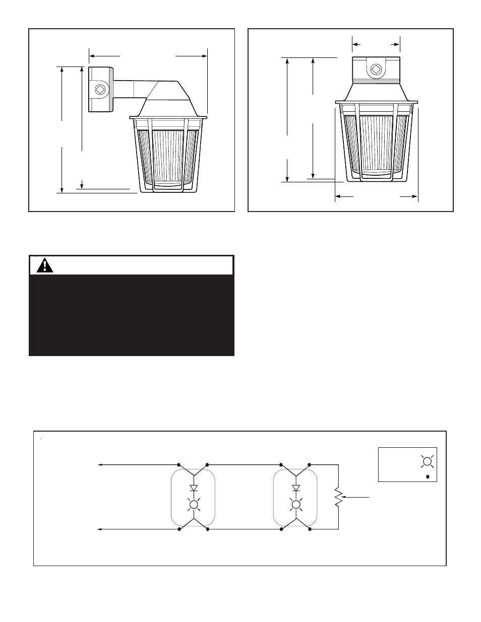
Figure 4. Wiring Diagram
NOTE: DC polarity of circuit shown in supervisory state (signal inactive). Circuit polarity to reverse to activate signal.
Electrical supervision requires wire run to be broken at each device.
Device for constant input voltage. Do not connect to “coded” or pulsating voltage.
From Power Source
or
Previous Signaling Device
End-of-Line Resistor,
when required with
supervised system
KEY:
Light symbol -
Wire nut symbol -
(+)
Red
(+)
Red
(+)
Red
(+)
Red
Black
(-)
Black
(-)
Black
(-)
Black
(-)
Series
107DDV2
Series
107DDV2
(+)
(-)
Maintenance
Maintenance
Maintenance
Maintenance
Maintenance
Disassemble the unit as follows (Figure 4):
1. Where applicable, remove the guard by rotating
counterclockwise.
2. Unscrew and remove the clear outer globe.
3. To replace the strobe tube, remove the inner lens and
replace the appropriate tube as listed in Table 1.
4. Reinstall the inner lens. Screw the clear outer globe
back onto the fixture housing.
5. Where applicable, install the guard assembly over the
clear outer globe by rotating clockwise until it snaps
into place.
WARNING
To reduce the risk of ignition of hazardous atmo-
spheres and shock, keep assembly tightly closed
when circuits are energized.
To reduce the risk of ignition of hazardous atmo-
spheres and shock, disconnect from the supply and
circuit and allow five (5) minutes for stored energy to
dissipate before disassembling the unit.
NOTE:
For use without field wire supervision installer can tie the two red leads together and tie the two
black leads together.
10 1/2"
(267mm)
11 3/8"
(289mm)
10 7/8"
(276mm)
4"
(102mm)
10 1/8"
(260mm)
9 3/4"
(248mm)
7"
(178mm)