Ge security industrial, Ordering/electrical specifications, General specifications – Edwards Signaling 371 User Manual
Page 2: Mounting configurations, Accessories
www.ge-security.com/industrial
12345 SW Leveton Drive
Tualatin, OR 97062
Phone: 800-247-9447
Fax: 503-691-7563
GE Security
Industrial
©2004 GE Security Industrial. GE Security Industrial reserves the right to change specifications without notice.
I-3893-0204 11510 Rev
E
Ordering/Electrical Specifications
PART NUMBER
CONTACT
1
LOAD RATING
SWITCHING VOLTAGE
SWITCHING CURRENT
CONTACT
NOMINAL SENSE RANGE
2
BREAK RANGE
TERMINAL
CONFIG.
AC/DC
MAXIMUM, AC/DC
MAXIMUM, AC/DC
RESISTANCE
Max. Min.
NOMINAL
TYPE
371-CT
N.O.
2.5VA/2.5W
[email protected] [email protected]
[email protected] [email protected]
0.5 Ohms
0.5"(1.3cm) 0.25"(0.635cm)
1.2"(3.0cm)
#6 Screws
371-DT
4
N.O.
150VA/NA
120V(@1.25A) NA
1.25A
3
(@120V) NA
NA
0.5"(1.3cm) 0.25"(0.635cm)
1.2"(3.0cm)
#6 Screws
Warning— Each electrical rating is an individual maximum and cannot be exceeded!
1
Configuration with actuator away from the switch
2
Proximity of ferrous materials usually reduces sense range — typically by 50%. The shape and type of material cause a wide diversity of effects.
Testing is required to determine actual sense range for specific applications.
3
Can withstand inrush surge up to 4 amps. Voltage drop is 1.5V. Minimum Switch Current 30mA.
4
Do not exceed 10 switches in series.
General Specifications
Enclosure
UL Explosion Proof, Die Cast Aluminum
Class I, Group B, C
Class II, Group E, F, G
Class III, Divisions 1 & 2
Temperature Range
-40
°
F to 180
°
F (-40
°
C to 80
°
C)
Environmental
Hermetically Sealed Contact Switch
Encapsulated in Polyurethane
NEMA Rating
1, 2, 5
Protection Class
IP 64
Response Time
1 msec (5.4VA); 10 msec (150VA)
Life Cycles
100,000 Under Full Load;
Up to 200,000,000 Under Dry Circuit
Conduit Connection
1/2" Threaded NPT
UL
All Models
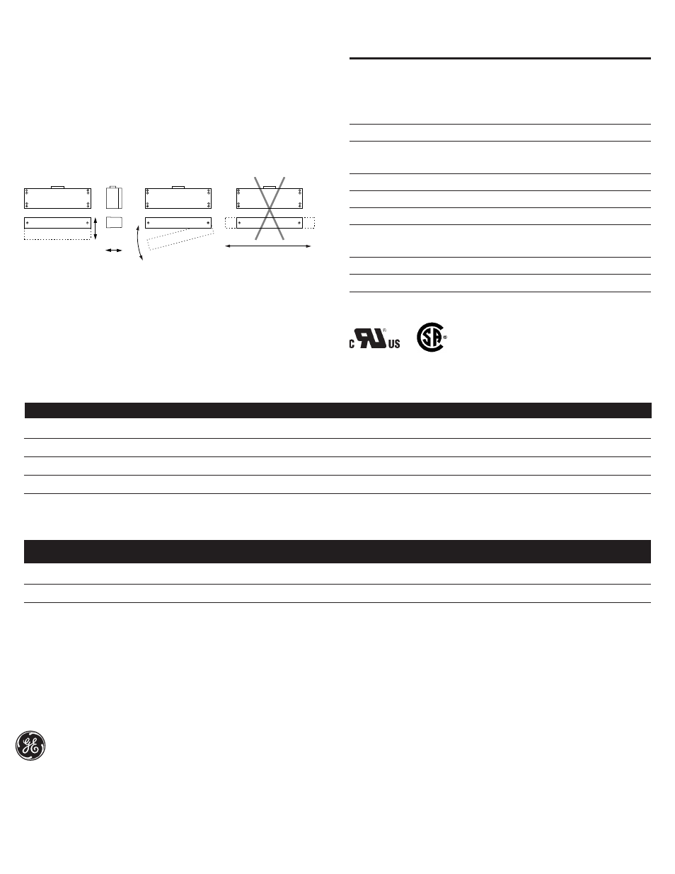
Perpendicular
Actuation
Door
Actuation
Parallel Actuation
Best
Best
Not Recommended
Pivot Actuation
Good
Figure 2
Mounting Configurations
The parallel actuation can result in on/off/on signal if the actuator passes by the
switch rather than coming to rest in proximity to it. This is NOT a recommended
configuration for safety interlock applications.
File E 122942
Accessories
PART NUMBER
TAMPER PROOF SCREWS & SCREWDRIVER
1953
#6 x 3/4"L Tampruf
Roundhead Screw
1954
#8 x 1-1/2"L Tampruf Roundhead Screw
1955
Tampruf
®
Screwdriver
1956
Tampruf
®
1/4" Drive Bit for #6 and #8 Screws
LR89176-19
4. For best protection against operator defeat, mount with
non-removable screws, bolts or nuts (see Accessories).
5. When mounting a metal switch to an ungrounded machine, connect the ground lead
to one of the switch mounting screws.
triac
output