Wiring – Edwards Signaling E-IDC1A User Manual
Page 2
2 / 4
P/N 3101191 • REV 02 • REB 25JAN13
Refer to “Specifications” for available address numbers.
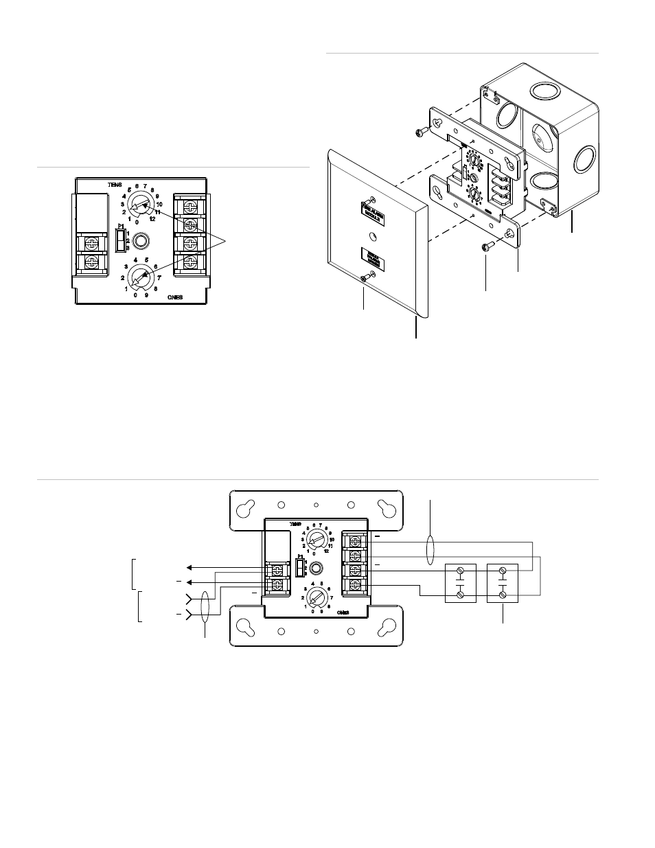
4. Set slide switch P1 to appropriate setting. Refer to
“Operation.”
5. Mount the module on the electrical box using screws
provided with the electrical box.
6. Mount the wall plate on the module using #4-24 x 1/2 in.
(13 mm) self-tapping screws.
Figure 2: Module address
Insert
screwdriver
here
Figure 3: Module installation
Screw
4-24
screws
Module
Wall plate
Compatible
electrical box
Wiring
Wire in accordance with NFPA 72 and CAN/ULC-S524. Be
sure to observe the polarity of the wires as shown in the
diagram.
Figure 4: Module wiring
TB2
TB1
(+)
(+)
(+)
(+)
RETURN
IDC
Typical NO
Initiating device
Style D Class A
[1] [2] [4]
[3]
To next
device
From
previous
device
SLC out
SLC out
SLC in
SLC in
SLC
(+)
( )
( )
( )
( )
( )
[1] Maximum 25
Ω resistance per wire
[2] Maximum 12 AWG (2.5 sq. mm) wire; minimum 18 AWG (0.75 mm
2
) wire
[3] Refer to the control panel technical reference manual for wiring specifications
[4]
Maximum 10 VDC at 350 μA
5.
All wiring is power-limited and supervised
6.
This module will not support two-wire smoke detectors