Specifications – Edwards Signaling FSRSI Remote System Indicator User Manual
Page 2
2 / 2
P/N 3101034 • REV 02 • REB 25JAN13
Notes
1. All wiring is supervised and power-limited
[2] AUX power supplied by the control panel can’t exceed 0.5
A. If more than 0.5 A is required, you must use a power-
limited and regulated 24 VDC auxiliary/booster power
supply that is UL/ULC Listed for fire protective signaling
systems.
[3] If powered from an external supply, the supply must be
installed in the same room as the control panel and their
24 VDC commons (−) wired together
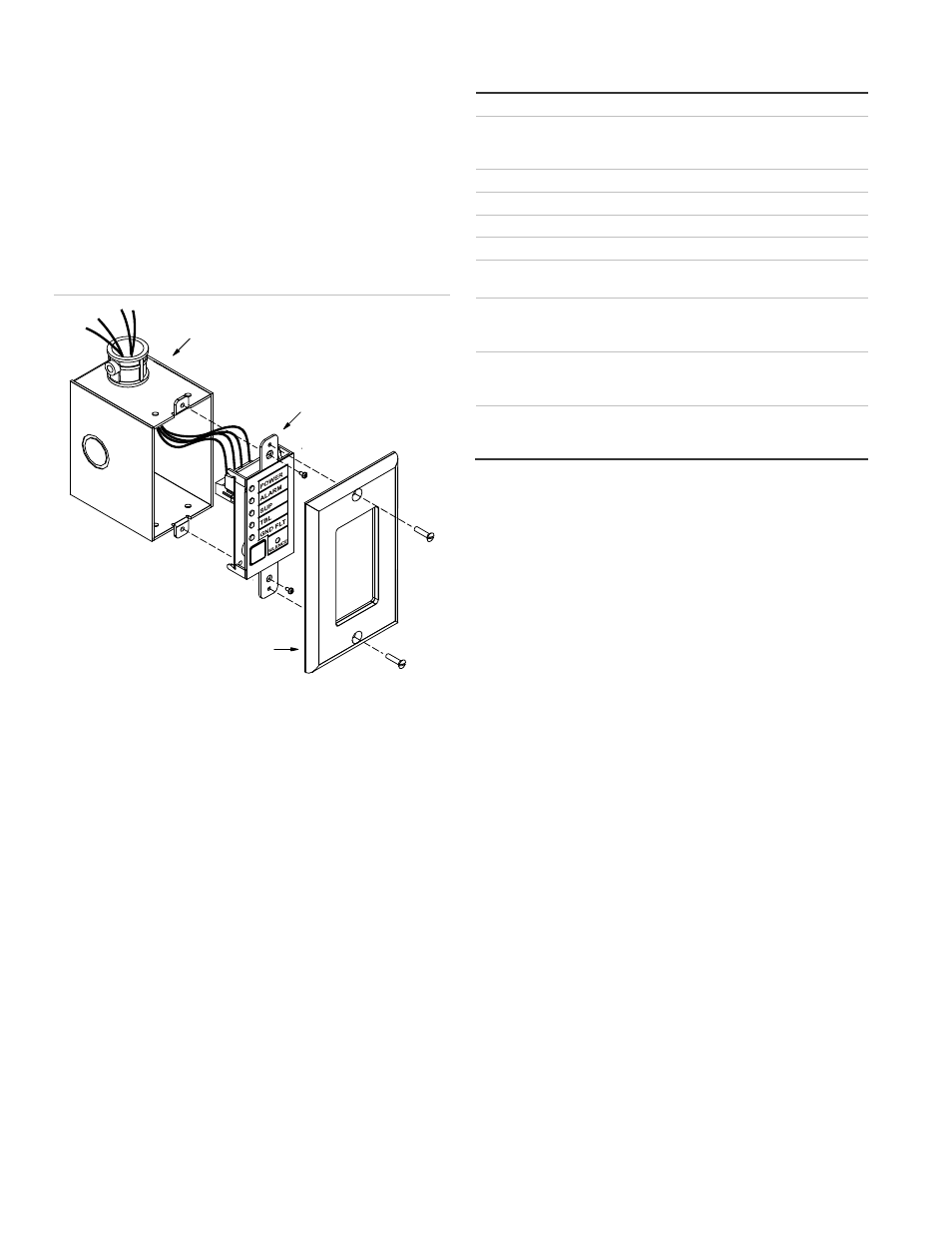
Figure 2: Installing the FSRSI in a single-gang electrical box
Specifications
Voltage
18.8 to 27.3 VDC
Current
Standby
Alarm
17 mA at 24 VDC
56 mA at 24 VDC
Circuit capacitance
0.03 µF, max.
Circuit resistance
13 ohms, max.
Ground fault impedance
0 Ω
Wire size
12 to 18 AWG (0.75 to 2.5 sq mm)
Compatible electrical box
ANSI/NEMA OS1-1996, 1- to 4-gang
electrical box
LED indicators
AC power (green), alarm (red),
supervisory (yellow), trouble (yellow),
ground fault (yellow)
Buzzer operation
Steady (trouble event), temporal (alarm
event), slow pulse (supervisory event),
intermittent (AC fail event)
Operating environment
Temperature
Relative
Humidity
32 to 120°F (0 to 49°C)
0 to 93% RH, noncondensing
Compatible 1-gang electrical box
FSRSI
FSAT1