Specifications – Edwards Signaling FSRZI-A-SA Remote Zone Indicators User Manual
Page 2
2 / 2
P/N 3101032 • REV 02 • REB 25JAN13
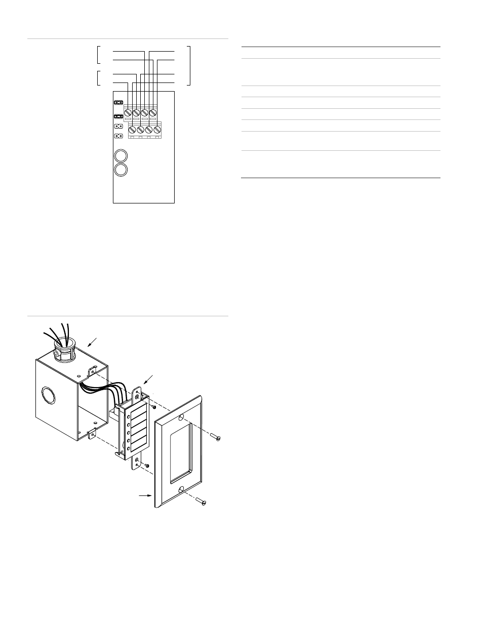
Figure 1: Wiring diagram
1.
All wiring is supervised and power-limited.
[2] AUX power supplied by the control panel can’t exceed 0.5 A. If
more than 0.5 A is required, you must use a power-limited and
regulated 24 VDC auxiliary/booster power supply that is UL/ULC
Listed for fire protective signaling systems.
[3] If powered from an external supply, the supply must be installed
in the same room as the control panel and their 24 VDC
commons (−) wired together.
Figure 2: Installing the remote zone indicator in a single-gang
electrical box
Specifications
Voltage
18.8 to 27.3 Vdc
Current
Standby
Alarm
8 mA at 24 VDC
76 mA at 24 VDC
Circuit capacitance
0.03 µF, max.
Circuit resistance
13 ohms, max.
Ground fault impedance
0 ohms
Wire size
12 to 18 AWG (0.75 to 2.5 sq mm)
Compatible electrical box
ANSI/NEMA OS1-1996, 1- to 4-gang
electrical box
Operating environment
Temperature
Relative
humidity
32 to 120°F (0 to 49°C)
0 to 93% noncondensing
J5
J4
J3
J2
Regulated 24 VDC
from control panel or
external power supply
[2] [3]
From
control panel
C
C
To
next remote
module
C
C
Compatible 1-gang electrical box
FSRZI-A
or
FSRZI-SA
FSAT1