Maintenance, Specifications, Regulatory information – Edwards Signaling Genesis High Candela Ceiling Speaker-Strobe User Manual
Page 3: Contact information
P/N 3100615 • REV 05 • REB 30JAN13
3 / 4
Table 3: Strobe operating current in RMS (A)
95 cd
115 cd
150 cd
177 cd
VDC
0.330
0.392
0.502
0.565
VFWR
0.432
0.518
0.643
0.693
VDC = Volts direct current, regulated and filtered
VFWR = Volts full wave rectified
Operating currents shown above were measured by UL at 16 VDC and
16 VFWR.
Table 4: Sound level output (dBA)
25V (UL)
25V (ULC)
70V (UL)
70V (ULC)
1/4 W
80
78
80
81
1/2 W
84
81
84
81
1 W
87
87
87
87
2 W (UL)
90
91
2.2 W (ULC)
90
90
UL1480: Sound level output at 10 ft (3.05 m) measured in a
reverberant room using 400 to 4,000 Hz band limited pink noise.
Directional characteristics: Within 6 dB of on-axis sound level when
measured 90
° off-axis (horizontal).
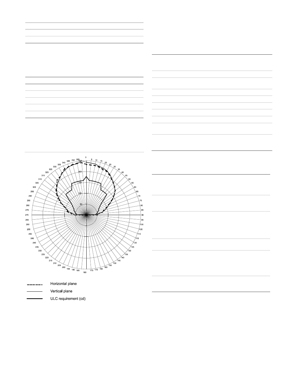
Figure 6: Light output profile
Maintenance
This unit is not serviceable or repairable. Should the unit fail to
operate, contact the supplier for replacement.
Perform a visual inspection and an operational test twice a
year or as directed by the local authority having jurisdiction.
Do no change the factory-applied finish.
Specifications
Operating voltage
Speaker
Strobe
25 VRMS (model S2) or 70 VRMS (model S7)
24 VDC, 24 VFWR
Supervisory voltage
30 V maximum
Strobe operating
current
See Table 3
Sound level output
See Table 4
Speaker response
400 to 4,000 Hz
Light output
Selectable at 95, 115, 150, and 177 cd
Default settings
1 flash per second (fps)
Wire size
12 to 18 AWG (0.75 TO 2.50 mm²)
Compatible electrical
boxes
North American 4 in. square electrical box,
2-1/8 in. min. deep
Operating environment
Temperature
Relative humidity
32 to 120°F (0 to 49°C)
0 to 93% noncondensing
Regulatory information
Manufacturer
Edwards, A Division of UTC Fire & Security
Americas Corporation, Inc.
8985 Town Center Parkway, Bradenton, FL
34202, USA
Year of
manufacture
The first two digits of the DATE MFG number
(located on the product identification label) are
the year of manufacture
UL/ULC rating
Regulated 24 DC, regulated 24 FWR
This device was tested to the regulated
24 DC/FWR operating voltage limits of 16 V and
33 V. Do not apply 80% and 110% of these
values for system operation.
Environmental
class
UL: Indoor dry
Synchronization
Meets UL 1971 requirements. Maximum allowed
resistance between any two devices is 20
Ω.
Refer to specifications for the synchronization
control module, this strobe, and the control panel
to determine allowed wire resistance.
Agency listings
UL 1480. UL 1638 and UL 1971
CAN/, ULC-S541, ULC S526
BS EN 60065:2002 [1]
[1] Nameplate marking is located on the inside surface of the device.
Contact information
For contact information, see www.edwardsutcfs.com.