Specifications, Regulatory information, Contact information – Edwards Signaling Genesis Chime-Strobe User Manual
Page 3
P/N 3100562 • REV 2.0 • ISS 19AUG10
3 / 4
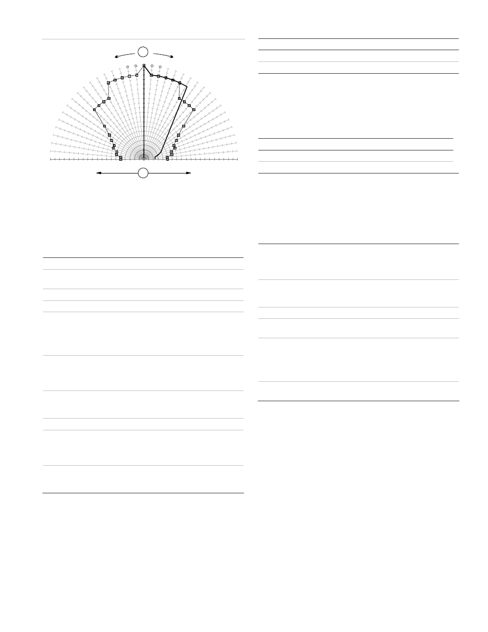
Figure 5: UL 1971 minimum light output (% of rating vs. angle)
100
95
90
85
80
75
70
65
60
55
50
45
40
35
30
25
20
15
10
5
0
5
10
15
20
25
30
35
40
45
50
55
60
65
70
75
80
85
90
95
100
0
5
10 15
20
25
30
35
40
45
50
55
60
65
70
75
80
85
90
-5
-10
-15
-20
-25
-30
-35
-40
-45
-50
-55
-60
-65
-70
-75
-80
-85
-90
1
2
1. Angle
2.
Minimum UL required candela light output
____ % of rated candela vertical specification
- - - - % of rated candela horizontal specification
Specifications
Voltage
24 VDC or 24 VFWR nominal
Strobe operating
current
See Table 3
Light output
Selectable at 15, 30, 75, and 110 cd
Sound level output
See Table 4
Default settings
Signal
Sound
level
output
Operation
Steady
High dB
Noncoded
Signals
Steady
Temporal
Coded
60 strokes per minute
3-stroke pattern
Maximum 60 strokes per minute
Operating modes
Noncoded
Coded
Continuous voltage
Single-stroke controlled by voltage
Wire size
12 to 18 AWG (0.75 TO 2.50 mm²)
Compatible electrical
boxes
2-1/2 in. (64 mm) deep single-gang box
4 in. square box 1-1/2 in. (38 mm), 2-gang
4 in. octagonal with G1T or G1RT trim
accessory
Operating environment
Temperature
Relative
humidity
32 to 120°F (0 to 49°C)
0 to 93% noncondensing
Table 3: Strobe operating current in RMS (A)
15 cd
30 cd
75 cd
110 cd
VDC
0.099 0.134 0.233 0.277
VFWR
0.154 0.195 0.338 0.383
VDC = Volts direct current, regulated and filtered
VFWR = Volts full wave rectified
Operating currents shown above were measured by UL at 16 VDC and
16 VFWR.
Table 4: ULI Ratings, temporal output (private mode)
Signal High
db
Low
db
Temporal 56.9
52.5
Steady 58.2 52.8
dBA = Decibels, A-weighted
UL464: Sound level output at 10 ft (3.05 m) measured in a reverberant
room at 16 V.
Regulatory information
Manufacturer
Edwards, A Division of UTC Fire & Security
Americas Corporation, Inc.
8985 Town Center Parkway, Bradenton, FL
34202, USA
Year of
manufacture
The first two digits of the DATE MFG number
(located on the product identification label) are
the year of manufacture
UL rating
Regulated 24 DC and 24 FWR
Environmental
class
UL: Indoor
Synchronization
Meets UL 1971 requirements. Maximum allowed
resistance between any two devices is 20
Ω.
Refer to specifications for the synchronization
control module, this strobe, and the control panel
to determine allowed wire resistance.
Agency listings
Meets UL1638, UL1971 (see Figure 1) and
UL464 (private mode)
Contact information
For contact information, see www.utcfireandsecurity.com.