Specifications, Regulatory information, Contact information – Edwards Signaling Genesis Signal Master Module User Manual
Page 2
2 / 2
P/N 3100124 • REV 08 • REB 30JAN13
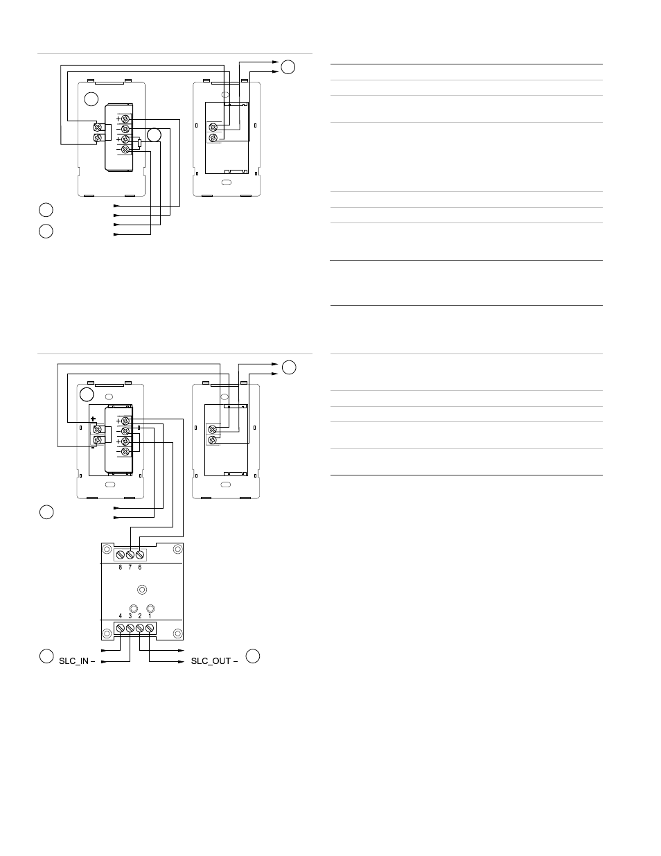
Figure 3: Horn silence / synchronization using two NACs
1.
NAC 1 horn in
2.
NAC 1 strobe in
3.
Horn resistor, value determined by the control panel
4.
Genesis appliance with Genesis Signal Master
5.
To next appliance. EOL resistor or Class A circuit return
Notes
•
Polarity shown in alarm condition
•
The horn circuit can be silenced without turning off strobes
Figure 4: Horn silence / synchronization using one NAC
1.
Signature data circuit from loop controller or previous device
2.
From previous appliance or control panel
3.
Genesis appliance with Genesis Signal Master
4.
To next appliance, EOL resistor or Class A circuit return
5.
To next device or Class A circuit return
Notes
•
EOL resistor is determined by the control panel requirements
•
Polarity shown in alarm condition
•
The horn circuit can be silenced without turning off strobes
•
CR module must be located in the same electrical box as the
Genesis Signal Master
Specifications
Operating voltage
16 to 33 VDC or 16 to 33 VFWR
Operating current
33 mA
Output rating
2 A max. Actual value limited by system NAC
and power outputs.
Synchronization
Flash
Resistance
between two
appliances
1/s, within 10 ms indefinitely
20 Ω max.
Wire size
12 to 18 AWG (0.75 to 2.50 mm²)
Mounting
Snaps to back of Genesis appliance
Operating environment
Temperature
Relative humidity
32 to 120°F (0 to 49°C)
0 to 93% noncondensing
Regulatory information
Manufacturer
Edwards, A Division of UTC Fire & Security
Americas Corporation, Inc.
8985 Town Center Parkway, Bradenton, FL
34202, USA
Year of
manufacture
The first two digits of the product serial number
(located on the product identification label) are
the year of manufacture.
UL rating
Regulated 24 DC, Regulated 24 FWR [1]
Synchronization
UL 1971 compliant
Environmental
class
UL: Indoor
North American
standards
UL 1971, UL 1638, UL 464, CAN/ULC S525,
CAN/ULC S526
[1] This module was tested to the regulated 24 VDC/FWR operating
voltage limits of 16 V and 33 V. Do not apply 80% and 110% of these
values for system operation.
Contact information
For contact information, see www.utcfireandsecurity.com.
-
-
+
STROBE_IN
+
STROBE
_IN –
2
HORN_IN
+
HORN
_IN –
H
S
4
3
1
5
+
+
-
+
C
NC
SLC_OUT +
CR
SLC_IN +
1
STROBE_IN
+
STROBE_IN –
2
H
S
4
3
5