Warning, Maintenance – Edwards Signaling 125XBR LED User Manual
Page 2
P/N 3101568 ISSUE 3
To avoid risk of injury, install lens before
energizing the unit.
To avoid the risk of injury, do not start any
maintenance when unit is energized.
WARNING
Maintenance
Cleaning
Disconnect power before cleaning. The module lens exterior
surfaces should be periodically cleaned with a soft clean
cloth using water and a mild detergent to maintain optimum
light visibility.
2. Turn on power and verify that the signal operates
properly.
Changing the Flash Mode
To change the flash mode from Steady-On to Flashing on
125XBRM beacons or from Steady-On to Lightburst on
125XBRZ beacons, connect the optional yellow wire as
follows:
- AC Models: Connect yellow wire to hot
- DC Models: Connect yellow wire to positive
NOTE: When using as shipped in Steady-On mode, cap
the yellow wire with a wire nut (supplied).
(See Figures 1 - 4 for details.)
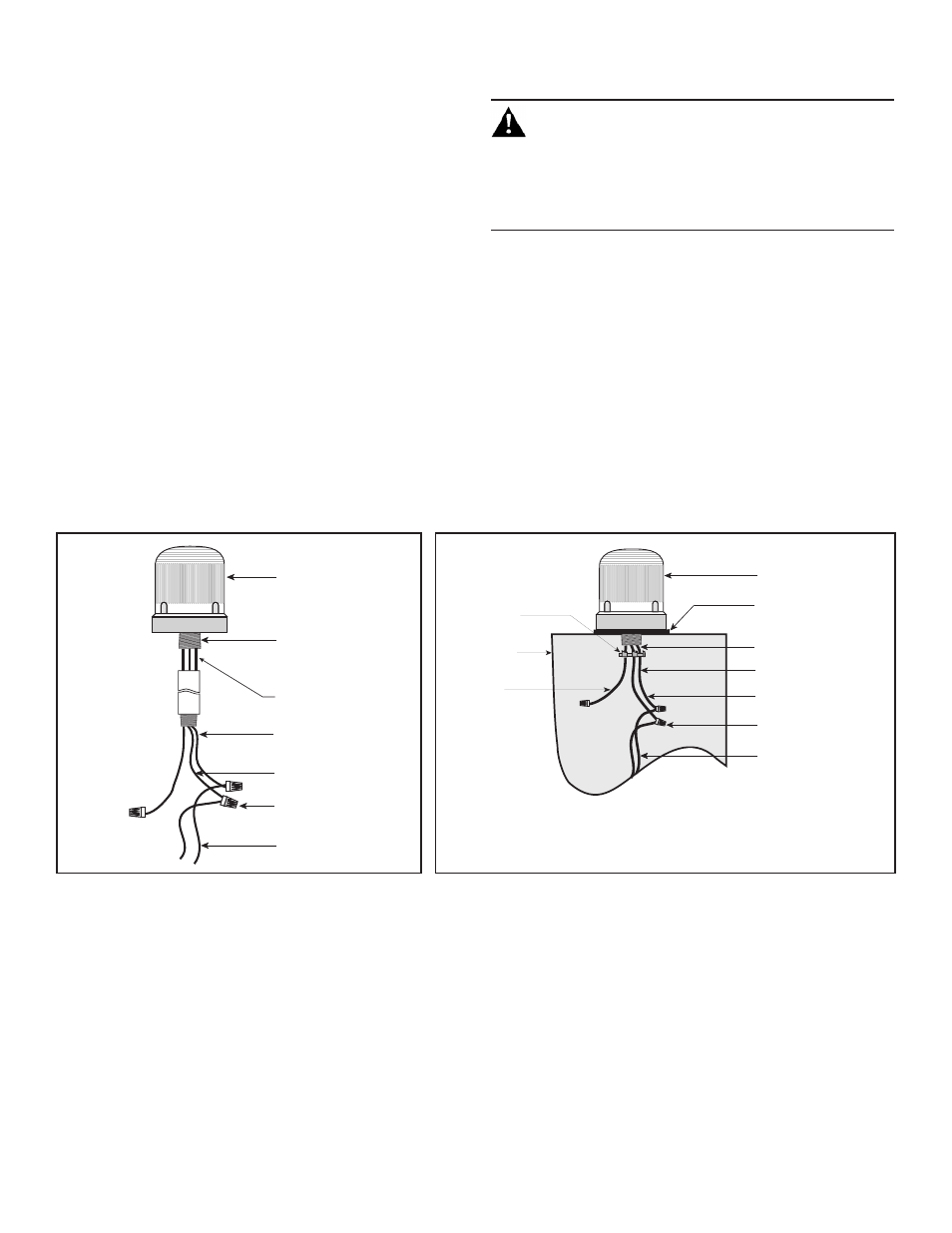
Figure 1. Conduit Mounting (3/4" Shown)
Figure 2. Panel Mounting
- Wiring for 125XBRM or 125XBRZ Steady-On Mode
- Wiring for 125XBRM or 125XBRZ Steady-On Mode
125XBR Series
LED Visual Indicator
DC units; Red positive (+),
AC units; Black Hot
DC units; Black negative (-)
AC units; White Neutral
Power Source
Wires
Yellow,
Not connected
(wire nut supplied)
18” Wire Leads
3/4” NPT external (shown)
1/2” NPT internal
conduit (not supplied)
Wire Nuts
(not supplied)
125XBR Series
LED Visual Indicator
Gasket
(supplied)
Locking Nut -
1.3625" OD
(supplied)
Control panel
(Enclosure)
Wire Nuts
(Not Supplied)
18” Wire Leads
Power Source
Wires
DC units; Red Positive (+)
AC units; Black Hot
DC units; Black negative (-)
AC units; White neutral
Yellow,
Not connected
(wire nut supplied)