Ge security industrial, General specifications, Ordering/electrical specifications – Edwards Signaling 113 GuardSwitch User Manual
Page 2: Wire color code
©2004 GE Security Industrial. GE Security Industrial reserves the right to change specifications without notice.
I-3899-0304 12519 Rev
C
www.ge-security.com/industrial
12345 SW Leveton Drive
Tualatin, OR 97062
Phone: 800-247-9447
Fax: 503-691-7563
GE Security
Industrial
General Specifications
Enclosure
ABS Plastic
Temperature Range
-40
°
F to 180
°
F (-40
°
C to 80
°
C)
Environmental
Hermetically Sealed Contact Switch
Sealed in Polyurethane
NEMA Rating
1, 2, 3, 4, 4X, 5, 6, 12
Protection Class
IP 67
Response Time
1 msec; 10 msec (150VA)
Life Cycles
100,000 Under Full Load;
Up to 200,000,000 Under Dry Circuit
Lead Types/O.D.
18/2 SJTOW(K)/0.30" (0.76cm)
18/3 SJTOW(K)/0.33" (0.84cm)
22/2 or 22/3 Jacketed (J)/O.24" (0.62cm)
UL/CSA
All Models
Ordering/Electrical Specifications
PART NUMBER
CONTACT
1
LOAD RATING
SWITCHING VOLTAGE
SWITCHING CURRENT
CONTACT
SENSE RANGE
2
BREAK RANGE
LEAD LENGTH
LEAD
CONFIG.
AC/DC
MAXIMUM, AC/DC
MAXIMUM, AC/DC
RESISTANCE
NOMINAL
NOMINAL
NOMINAL
SIZE
113-3Y-06(J)
N.C.
100VA/84W
3
3.0A
3
@34V 3.0A
3
@28V
1.0 Ohms
0.7"(1.8cm)
1.2"(3.0cm)
6'(1.8m)
22/2
113-3Y-12(J)
N.C.
100VA/84W
3
3.0A
3
@34V 3.0A
3
@28V
1.0 Ohms
0.7"(1.8cm)
1.2"(3.0cm)
12'(3.6m)
22/2
113-4Y-06(K)
SPDT
100VA/84W
3
3.0A
3
@34V 3.0A
3
@28V
1.0 Ohms
0.7"(1.8cm)
1.2"(3.0cm)
6'(1.8m)
18/3
113-4Y-12(K)
SPDT
100VA/84W
3
3.0A
3
@34V 3.0A
3
@28V
1.0 Ohms
0.7"(1.8cm)
1.2"(3.0cm)
12'(3.6m)
18/3
113-5N-01(J)
N.O.
7.5VA/NA
48V
48V
0.5A@48V 0.5A@48V
1.0 Ohms
0.7"(1.8cm)
1.2"(3.0cm)
1'(0.3m)
22/2
113-GN-01(K)1
N.C.
1.0 Ohms
0.7"(1.8cm)
1.2"(3.0cm)
1'(0.3m)
18/2
113-7Y-12(K)
N.O.
100VA/84W
3
3.0A
3
@34V 3.0A
3
@28V
1.0 Ohms
0.7"(1.8cm)
1.2"(3.0cm)
12'(3.6m)
18/2
113-Y
Actuator Only
Included with all switches unless otherwise noted.
113-Z
Actuator Only
Included with all switches unless otherwise noted.
Warning— Each electrical rating is an individual maximum and cannot be exceeded!
1
Configuration with actuator away from the switch
2
Proximity of ferrous materials usually reduces sense range — typically by 50%. The shape and type of material cause a wide diversity of effects.
Testing is required to determine actual sense range for specific applications.
3
Rated at 3.0A for 6,000 cycles only. Other ratings are at 100,000 cycles.
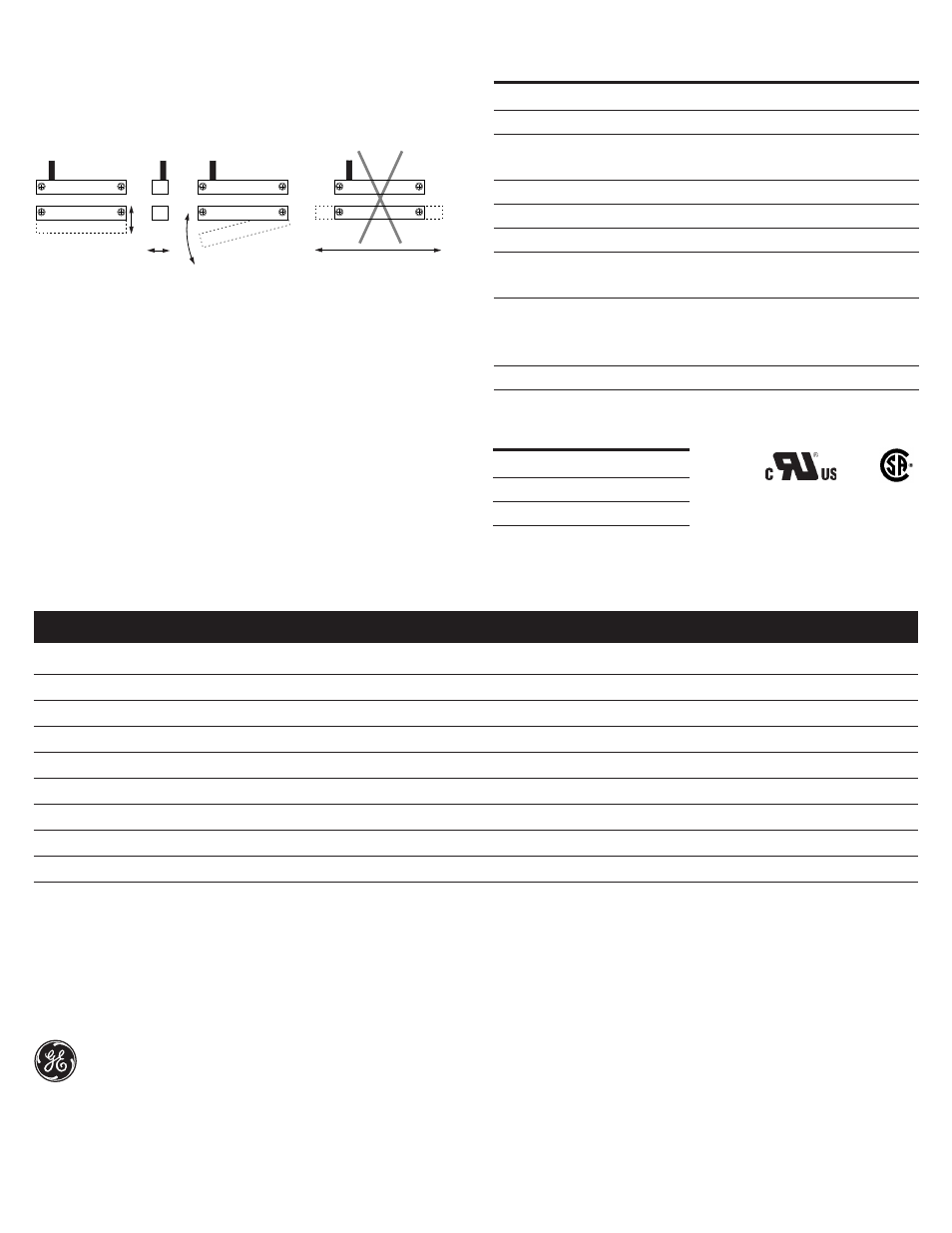
The interlock switch and actuator magnet should be mounted in only three
configurations for actuation:
File E 122942
LR89176
Parallel Actuation
Not Recommended
Three configurations are appropriate for interlock applications. The parallel
actuation can result in on/off/on signal if the actuator passes by the switch rather
than coming to rest in proximity to it. This is NOT a recommended configuration for
interlock applications.
Perpendicular
Actuation
Door
Actuation
Pivot Actuation
Best
Best
Figure 2
Good
Wire Color Code
Black
COM
White
N.O.
Red
N.C.