Figure 4. installing the adaptabel, surface mount, Figure 1. bell dimensions – Edwards Signaling 439D Series User Manual
Page 2
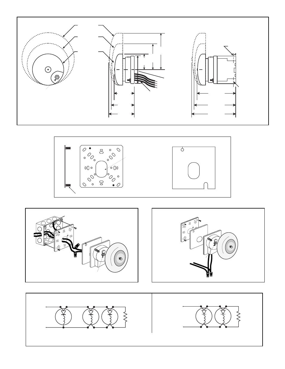
Figure 4. Installing the Adaptabel, Surface Mount
$GDSWDEHOO
Gong
Bell Body
Insulator
Mounting Plate
Attach green ground wire to appropriate earth
ground. Electrical box grounding shown for
illustration purpose only.
Grooves for
aligning gong
Figure 1. Bell Dimensions
Page 2
P/N P-047550-0590 ISSUE 6
Assemble bell base to mounting
plate with (2) lockwashers and
(2) nuts (supplied with bell)
9" Leads -
(2) black and (2) red.
1/4" stripped.
10" Gong
8" Gong
6" Gong
2 29/32"
(73.8 mm)
3 11/32"
(84.9 mm)
3 15/32"
(88.1 mm)
Center line
of base
7"
(177.8 mm)
5"
(127 mm)
3"
(76.4 mm)
5 1/16"
(128.6 mm)
5 1/2"
(139.7 mm)
5 5/8"
(142.9 mm)
Base
4 5/8"
(117.5 mm)
11/16"
(17.5 mm)
Outlet 3/4" (19 mm)
Outlet 3/4" (19 mm)
Optional
weatherproof box
Cat. No. 449
Insulator
TOP
Front View
Side View
For wall box mounting:
Use bell wire exit hole in mounting
plate for bringing bell lead wires out
for connections in electrical outlet box
For surface mounting:
Use wire entrance hole in bell body for
circuit wiring to bell lead connections.
Place connections in bell housing,
behind insulator.
(2) Studs
Figure 2. Metal Mounting Plate and Insulator
Figure 3. Installing the Adaptabel, Wall Mount
Blk
Blk
Red
Red
From supervised
signal circuit or
previous appliance
End of line
resistor
Blk
Blk
Blk
Blk
Red
Red
Wht
From supervised
signal circuit or
previous appliance
End of line
resistor
NOTE: Use leads for connections as shown. Wire run MUST be broken to provide supervision of signal
circuit.
Wiring for 4-wire bells to existing 3-wire signal circuit
Wiring for 4-wire bells
Figure 5. Wiring Diagrams
Insulator
Mounting Plate
$GDSWDEHOO
Gong
Bell Body
Grooves for
aligning gong