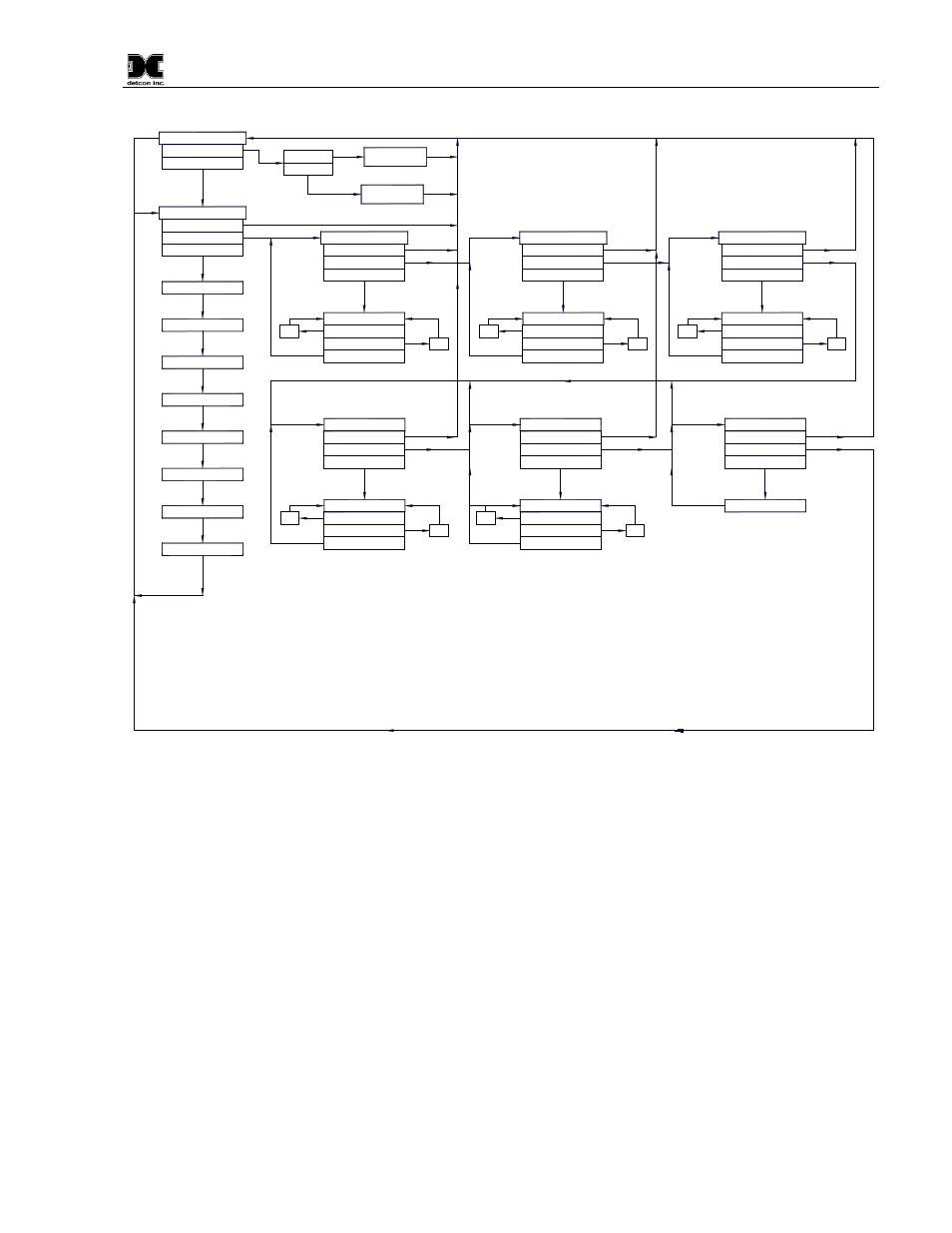
Software flowchart, 2 normal operation, 3 calibration mode – Detcon CX-IR User Manual
Page 17: Normal operation, Calibration mode, Figure 11 software flow chart, Figure 12 software flow chart
Model CX-IR
Software Flowchart
dec
LEGEND:
PGM1 - Program Switch Location #1
PGM2 - Program Switch Location #2
(S) - Momentary Swipe
(M) - Momentary hold of Magnet during text
scroll until the ">" appears, then release
(3) - 3 second hold from ">" prompt
(10) - 10 second hold from ">" prompt
Auto Time-out - 5 seconds
inc - Increase
dec - Decrease
#, ##, ### - numeric values
AutoZero
PGM1 (3)
PGM2 (10)
PGM2 (3)
inc
Auto Time-Out
View Sensor Status
PGM1/2 (3)
PGM1/2 (M)
PGM2 (S)
PGM1/2 (3)
PGM1 (S)
##
AutoTime-out
PGM1/2 (3)
PGM1/2 (M)
Set Gas Type
AutoSpan
Normal Operation
PGM1 (3)
Auto Time-Out
Auto Time-Out
inc
PGM2 (S)
PGM1/2 (3)
PGM1 (S)
##
PGM1/2 (3)
PGM1/2 (M)
Set Autospan Level
dec
inc
PGM1/2 (3)
PGM1 (S)
PGM2 (S)
##
dec
PGM1/2 (3)
PGM1/2 (M)
Set Gas Factor
Status is CX-IR V
Serial Number
Range ###
Auto Span Level ##
Modbus ID ##
Last Cal # Days
Sensor Life ###
Temperature ##
PGM1/2 (M)
Defaults Restored
PGM1/2 (3)
Restore Defaults
Auto Time-Out
dec
inc
PGM2 (S)
PGM1/2 (3)
PGM1 (S)
##
AutoTime-out
PGM1/2 (3)
PGM1/2 (M)
Set Modbus ID
dec
inc
PGM2 (S)
PGM1/2 (3)
PGM1 (S)
##
AutoTime-out
PGM1/2 (3)
PGM1/2 (M)
Bump Test
Figure 12 Software flow chart
3.2 Normal Operation
In normal operation, the Intelligent Transmitter Module (ITM) display will be blank and will display the gas
reading once every 10 seconds for about 2 seconds (normally appear as "0"). At any time, swiping a magnet
across either PGM1 or PGM2 will cause the ITM to display the range and gas type (i.e. "ppm H2S"). If the
sensor is actively experiencing any diagnostic faults, a swipe of the magnet will cause the display to scroll the
fault condition. Refer to Section 5 Service and Maintenance for more information on fault conditions.
3.3 Calibration Mode
Zero and span calibration should be performed on a routine basis (quarterly minimum is advised) to ensure
reliable performance. If a sensor has been exposed to any de-sensitizing gases, or to very high over-range
combustible gas levels, re-calibration should be considered. Unless otherwise specified, span adjustment is
recommended at 50% of the full scale range.
To enter calibration mode hold the magnet over PGM1 for 3 seconds. If the sensor is experiencing a fault
condition the "
►" prompt will not appear until the fault(s) have been displayed. When the ITM enters
CX-IR Instruction Manual
Rev. 1.2
Page 13 of 34