1 terminal connections 3-wire 4-20ma, 2 terminal connections 4-20ma and rs-485, Terminal connections 3-wire 4-20ma – Detcon CX-IR User Manual
Page 12: Terminal connections 4-20ma and rs-485, Figure 7 sensor wire connections, Remove the junction box cover
Model CX-IR
NOTE 1: Wiring table is based on stranded tinned copper wire and is designed to serve as a
reference only.
NOTE 2: Shielded cable is required for installations where cable trays or conduit runs include
high voltage lines or other possible sources of induced interference. Separate conduit runs are
highly recommended in these cases.
NOTE 3: The supply of power should be from an isolated source with over-current protection
as stipulated in table.
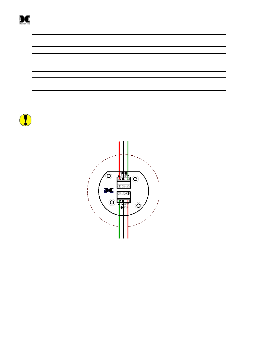
2.5.1 Terminal Connections 3-Wire 4-20mA
CAUTION: Do not apply System power to the sensor until all wiring is properly terminated. Refer to
Section 2.5 Initial Start Up
mA
(+
)
(-)
Wiring to
Sensor Assembly
G
ree
n
R
ed
B
lk
Explosion
Proof
Junction Box
(+
)
mA
(-)
Wiring to
Controller
R
ed
G
rn
B
lk
Detcon Inc.
Rev. 1
440-005208-000
MODULE
PROTECTION
TRANSIENT
Figure 8 Sensor Wire Connections
a) Remove the junction box cover. Identify the terminal blocks for customer wire connections.
b) Observing correct polarity, terminate the 3-conductor 4-20mA field wiring (+, -, mA) to the sensor
assembly wiring in accordance with the detail shown in Figure 8.
c) Replace the junction box cover.
2.5.2 Terminal Connections 4-20mA and RS-485
1. Remove the junction box cover.
CX-IR Instruction Manual
Rev. 1.2
Page 8 of 34