Hardware connections, Grounding considerations, Signal and shielding – AW Gear Meters EMO-500 User Manual
Page 12
EMO-500
Operation and Programming Manual
11
Hardware Connections
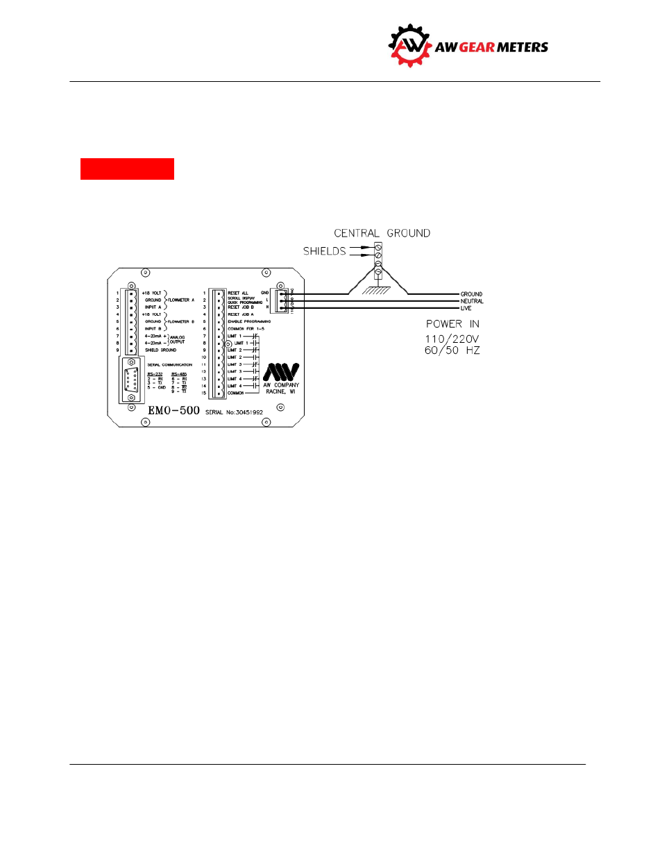
Before connecting to power source, connect ground, neutral and live wires to terminals on back of the
EMO-500: PIN 1= ground, PIN 2 = line 110 or 220 V, and PIN 3 = line neutral
(see Figure 3).
Wire the AC power only as labeled on the three pin connector
.
Figure 3: Connections to power
Grounding Considerations
The grounding is a most important consideration in an installation where microprocessor technology is
applied. The EMO-500 is a panel-mounted unit where the casing connects to a sub-panel. If the
sub-panel is metal, it should be grounded. If the sub-panel is made of non-conductive material, PIN 1 of
the three-pin connector on the EMO-500 back panel must be grounded
.
To insure a proper ground, the
factory recommends connecting PIN 1 of the three-pin connector to the panel's central ground point.
Signal and Shielding
The two flow meter pickups should be supplied with their respective 18-volt supply voltages and
referenced to their respective grounds. This insures the input signals from the flow meters are
referenced to the ground connections on pins 2 and 5. Most applications require some signal shielding;
a solid-aluminum wrap shielding works well. Connect the shield to pins 2 and 5 on the flow meter
connector. DO NOT connect the shielding at the flow transmitter.
Warning!