Rt‐15 flow monitor, Rate a / total a display mode, C yc le o ut (pulse o utput) lim it fu n c tio n – AW Gear Meters RT-15 User Manual
Page 28
RT‐15 Flow Monitor
Operation and Programming Manual
27
When considering a large cycle amount, keep in mind that any external totalizer misses at least one cycle
amount of accumulation whenever power is cycled to the RT‐15.
To program limit functions, use the MODE/DN button (or magnetic switch) to select the LIMIT display.
Press and hold the ENT button (or maintain the ENT magnetic switch). The display first shows a P in the
lower left‐hand corner and then highlights the L1 indication with a blinking cursor. Use the SEL button or
magnetic switch to select the function of the limit assignment. Use the ENT button (or magnetic switch)
when the desired mode displays for L1. The cursor now highlights the numeric value to be entered for
L1. Entries correspond with the scaling factor, decimal location, and engineering units for the function
selected. The blinking cursor highlights the left‐most digit. Move the cursor left to right using the SEL
button (or magnetic switch). Use the UP or DN button (or magnetic switch) to increase or decrease each
digit’s value. When editing is complete and the desired value displays, use the ENT button (or magnetic
switch) to store the value for L1.
If you have made a RATE assignment, the RT‐15 next prompts you to enter the RATE LIMIT MARGIN in
percent. The blinking cursor highlights the left‐most digit. Move the cursor using the SEL button (or
magnetic switch). Use the UP or DN button (or magnetic switch) to increase or decrease each digit’s
value. When you have completed editing and the value displays, use the ENT button (or magnetic
switch) to store the RATE LIMIT MARGIN. A blinking cursor then highlights the L2 indication. Repeat the
procedures for L1. When you have completed the L2 programming, use the ENT button (or magnetic
switch) to store the values and exit LIMITS programming.
See Wiring Connections and Connection Diagram on page 11 for information regarding connection to
limit outputs.
RATE A / TOTAL A Display Mode
View RATE A GT and TOTAL A (Job Total) on the same screen using the RATE A_TOT A display. The RT‐15
displays rates and totals in the corresponding engineering units based on the programmed KFR and KFT
factors and decimal locations. To view the GR TOTAL, use the SEL button (or magnetic switch) to switch
between TOTAL A (TA) display and GR TOTAL A (GA) as illustrated below. After a power cycle, the RT‐15
Notice
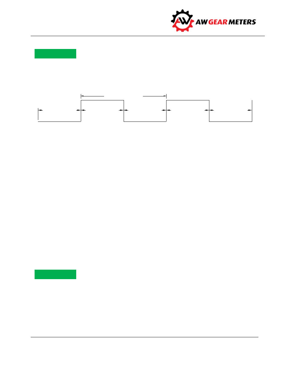
C YC LE A M O UN T
C YC LE A M O UN T
C YC LE A M OUN T
C YC LE A M OUN T
C YC LE A M O UN T
LIM IT O N
LIM IT O N
LIM IT O FF
LIM IT O FF
LIM IT O FF
2 x C YC LE A M O UN T
C YC LE O UT (PULSE O UTPUT) Lim it Fu n c tio n
Notice