AW Gear Meters RT-15 User Manual
Page 19
RT‐15 Flow Monitor
Operation and Programming Manual
18
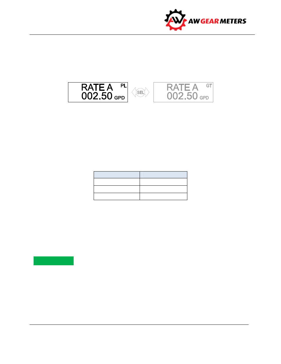
RATE A Pulse Length (RATE A PL)
The rate is calculated by the pulse length method based on the SAMPLE A variable. It is displayed based
on the corresponding KFR factor, decimal location, and engineering units. View the gate time
measurement RATE A GT by using the SEL button (or magnetic switch) while in the RATE A PL display as
illustrated below. The rate display reverts to RATE A PL if power is cycled to the RT‐15. A typical display:
RATE Mode Programming
Program the Rate parameters from the RATE A GT or RATE A PL display screen. Also program RATE A PL
variables from the RATE A GT screen, or vice versa, by toggling to the RATE A PL mode using the SEL
button (or magnetic switch). Use the MODE/DN button (or magnetic switch) to select the RATE GT
display. Press and hold the ENT button or maintain the ENT magnetic switch. The display first shows a P
in the lower left‐hand corner and then displays the first program variable for that rate display mode. You
can access three parameters for either mode as follows:
RATE A
GT
RATE A
PL
KFR A VALUE
KFR A VALUE
GATE A B
SAMPLE A
ENG UNITS A
ENG UNITS A
KFR A Value
Scaling factor to display rate in a desired engineering unit such as GPM. The KFR factor entered here also
determines the decimal resolution of the rate display. The KFR is calculated using the K‐factor of the
transducer being monitored. The K‐factor is the number of impulses per engineering unit established by
the transducer manufacturer or by a calibration test.
The AW Gear Meters Calibration sheet provides the K‐factor and recommended KFR values.
Initial default is: 100.00 (displays Hertz to two decimal places)
The KFR factor is calculated using the following formula:
Notice