Rt‐15 flow monitor, Display/programming buttons and magnetic switches, Operation and programming manual – AW Gear Meters RT-15 User Manual
Page 14: D ispla y/pro gra m m in g b utto n lo c a tio n s, M a gn etic sw itc h lo c a tio n s
RT‐15 Flow Monitor
Operation and Programming Manual
13
Maximum signal amplitude: 10 Volts peak.
Frequency: 0‐4000Hz
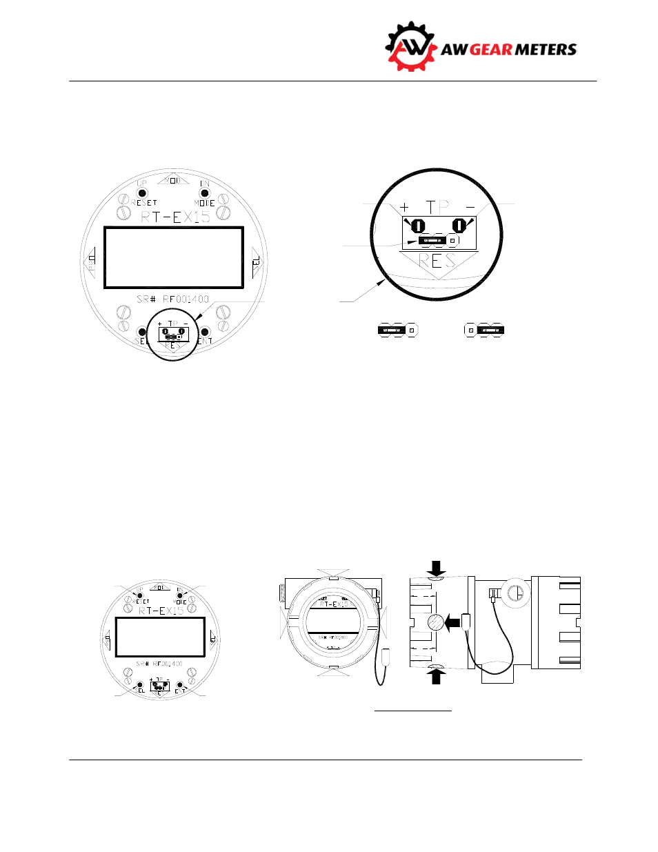
Figure 4: Test Points and Jumper Settings
Display/Programming Buttons and Magnetic Switches
Use the buttons on the faceplate when the cover is off, or the magnetic switches when the cover is on,
to program the unit, change the display, and reset total. The magnetic switches are located at the 3, 6, 9
and 12 o’clock positions on the side of the housing. See the faceplate of the RT‐15 for the function of
each position. Touching the side of the magnet wand to the appropriate location activates the magnetic
switches.
C A LIB RA TIO N
TEST PO IN TS
& JUM PER
RA 002.50
TA 003.23
GPD
GAL
GT
N o rm a l
O p e ra t io n
Ju m p 1 & 2
1
2
3
1
2
3
Te s t Po in t
O p e ra t io n
Ju m p 2 & 3
JUM PER SETTIN GS
Te s t Po in t (- )
(Iso la t e d
Su p p ly
C o m m o n )
Pro g ra m
Ju m p e r
Te st Po in t (+ )
(Sig n a l In p u t )
M A GN ETIC
SW ITC H
(EN T)
GT
GAL
GPD
RA 002.50
TA 003.23
M A GN ETIC
SW ITC H
(SEL)
M A GN ETIC
SW ITC H (RESET/UP)
M OD E/D N
B UTTO N
RESET/UP
B UTTON
SEL
B UTTON
EN T
B UTTO N
D ISPLA Y/PRO GRA M M IN G
B UTTO N LO C A TIO N S
RA 002.50
TA 003.23
GPD
GAL
GT
1
1
4
1
1
4
D N /
M O D E
R E S ET
EN T
U P /
S E L
M A GN ETIC SW ITC H LO C A TIO N S
TO UC H SID E O F M A GN ET TO SW ITC H LO C A TIO N
M A GN ETIC
SW ITC H (M OD E/D N )