5 control system auxiliary – Hired-Hand Emergency Back-Up and Alarms: Secondary Sensing System User Manual
Page 11
Manual No. 4801- 2997 Rev 7-08
Secondary Sensing System
11 of 40
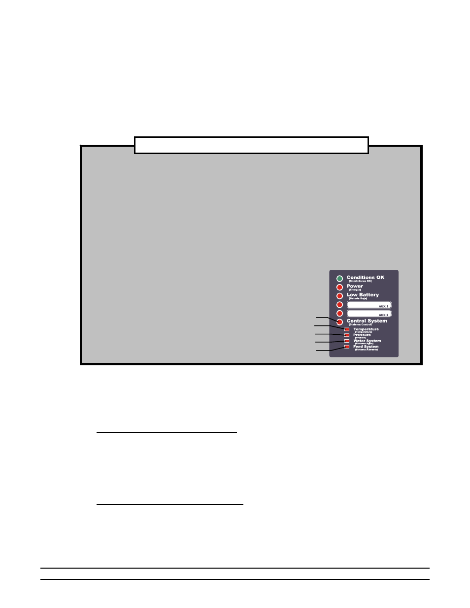
Control System
TEMPERATURE:
The temperature is beyond the alarm limits.
PRESSURE:
Indicates a High, Low, or Cycle Pressure alarm.
WATER SYSTEM:
Indicates High or Low water usage.
FEED SYSTEM:
Indicates a feed auger excessive runtime alarm.
SPECIAL FEATURES IF USED WITH EVOLUTION 3000/3001
permanent fine-tipped marker. Each auxiliary alarm can be individually enabled or disabled by using the
circuit board jumpers. Refer to the Circuit Board Layout in Section 12.2. If the jumper is installed, the
AUX 1 or AUX 2 alarm is Disabled; If the jumper is removed, the AUX 1 alarm is Enabled.
5.2.5 Control System Auxiliary
The Control System auxiliary input is a special input that should be connected to the main control system.
It operates similar to Aux1 and Aux2 and yet has special functions associated with it to provide better
protection for the building. The functions are different when the unit is connected to an Evolution
3000/3001 and when it is connected to another type control system. The following details the differences.
Operation with Evolution 3000/3001:
If connected to a Evolution 3000/3001, there is a communication network that allows
communication of the alarm data from the main system to the S
3
. This allows the system to alarm
even if the hard-wired connection to the Control System Auxiliary does not exist. It also allows
the S
3
to provide more detail as to what problem exist using the four LEDs located just below the
Control System indication. The following picture highlights these indicators.
The CONTROL SYSTEM alarm can be enabled or disabled by using the circuit board jumpers.
Refer to the Circuit Board Layout in Section 12.2. If the jumper is installed, the CONTROL
SYSTEM alarm is Disabled; If the jumper is removed, the CONTROL SYSTEM alarm is
Enabled. The Evolution controller communicates with the S
3
to display the four alarms described
below:
Operation without the Evolution 3000/3001:
If the unit is used with another type control system, the Control System Auxiliary can take on other
functions on top of just being an alarm. This input can function in one of two ways depending on the
setting in program parameter P62 (See Section 6).
P62 = On – Cycle Pressure Alarm Enabled
If “P62 = On”, the input becomes a Cycle Pressure input. Therefore, while connected to a Photohelic, or
Static Pressure switch, it will monitor the static pressure through the timer cycle period (P63). If it does
not see a static pressure spike during this cycle, it will assume that the minimum ventilation is not working.
Therefore, it will sound the alarm and also trigger the Back-Up system to run the “Cool1” backup stage on
a minimum ventilation cycle. The minimum ventilation cycle is five minutes and the runtime will be based
on the setting in P3 (See Section 6).
P62 = OFF – Cycle Pressure Alarm Disabled
If “P62 = OFF”, the input is a normal auxiliary input that will function in much the same way as Aux1 and
Aux2. There is one distinction. If the S
3
detects the alarm signal on this input, it will not only sound the
alarm but it will also trigger the Back-Up System to run the “Cool1” backup stage on a minimum
ventilation cycle. The minimum ventilation cycle is five minutes and the runtime will be based on the
setting in P3 (See Section 6).