5 variable speed stage operation – Hired-Hand Farm Hand Series: Vent Master 16 Stage User Manual
Page 22
Part No. 4801-5098 Farm Hand Vent Master 19
As you can see, a stage will be placed on the system timer once the temperature rises above 80ºF
(OFF) and will start running 50% (P71) of the time. If the temperature continues to increase
then the run time percentage will also increase toward 90% (P70).
12.5 Variable Speed Stage Operation
Depending on the Farm Hand Vent Master model, you have 0 or 2 variable stages. The Variable stages
can be used in one of two ways: Variable Speed or Progressive Cool Timer. The two options are selected
by the parameters P3. The following sections explain the operation of both options.
12.5.1 Variable Speed Stage Operation (Variable Stage Model Only)
Note: This option applies to stages 1 and 2 of the Variable Stage Farm Hand Vent Master.
The variable speed option (P3=0) allows the user to configure the variable stage to vary the speed of the
fan for their minimum ventilation needs. The following explains the setup and operation.
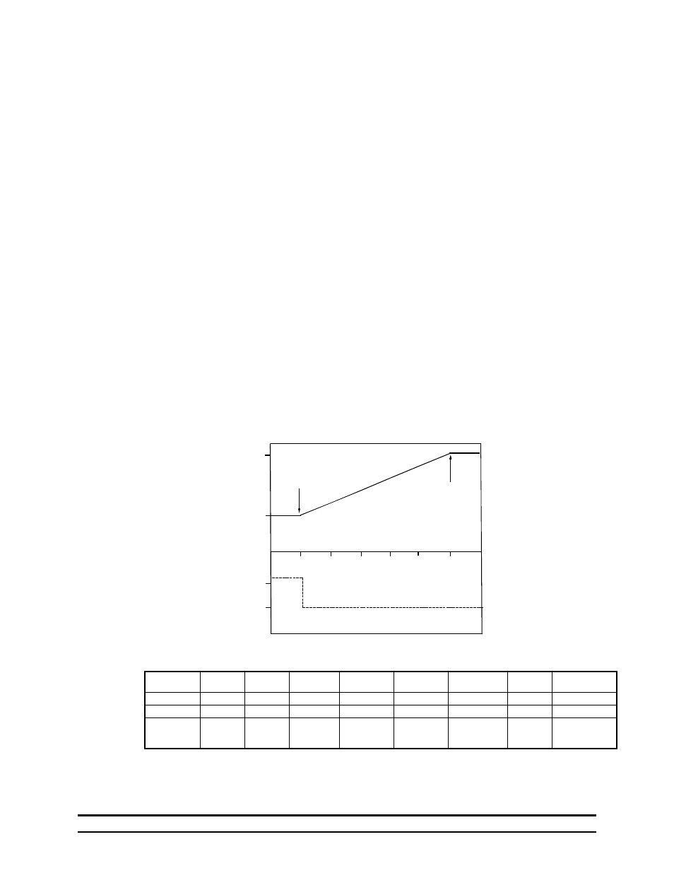
In this case, the stage timer setting is P3=0 to indicate variable speed operation. The Minimum OnPoint
(OFF) is set for 75ºF, and the Maximum OnPoint (ON) is set for 80ºF. This establishes the temperature
range (75º-80º) over which the speed is varied. The variable speed percentage is set by the "Var/Timer
Pct." parameter as described in Section 5.1. In this example, Var/Timer Pct. is set to 50%. The
Minimum Runtime percentage is set to 40% (P10=40).
Below 75ºF, a fan connected to the variable speed stage will run at 50% speed for 40% of the system timer
(either 2 minutes for a 5 minute timer, or 4 minutes for a 10 minute timer). When the temperature
reaches 75ºF, the fan will run at minimum speed (50%) continuously. As the temperature increases, the
fan speed progressively increases from 50% up to 100% at 80ºF. Above 80ºF, the fan runs continuously
at its maximum speed.
Table 2 Example Of Variable Speed Fan Control
Brief Description Of Variable Speed Fan Control
Percent
100
50
50
100
76
78
80
77
75
79
TEMPERATURE (F)
Graph 2 Variable Speed Fan
Minimum OnPoint
Minimum Speed
Maximum
Maximum Speed
Setting
Stage
Sensor
Stage
Mode
Stage
Timer
Minimum
OnPoint
Maximum
OnPoint
Minimum
Runtime %
Motor
Curve
Var/Timer
Percentage
Parameter
P1
P2
P3
OFF
ON
P10
P11
N/A
Value
10
02
00
75
80
40
0
50
Option
Sensor 1
Cool Stir
No Timer
Fan begins
Varying
Speed
Fan begins
Maximum
Speed
Runtime
40%
Standard
single
phase
Refer to
Section 5.1