Danger, Initial setup of variable output control board, 1 ev-var pcb 174 board – Hired-Hand Evolution Series 3000/3001: Variable Output With Override Pot User Manual
Page 6: Layout and setting locations
Part No. 4801-5318 Rev 4-06
Evolution Variable Output
Page 6 of 14
6. Initial Setup of Variable Output Control Board
(PCB 174 rev C or later)
The following sub-sections describe the usage and settings of each connection, jumper, and switch included on the EV-VAR PCB
#174 revision C or later. The board layout with wiring/setting location references are shown in Section 6.1. The latest PCB174
revision C or later include the following product enhancements:
•
Sunset light control functionality is now provided along with the Sunrise feature which was available on the previous
version EV Variable Output controls. The Sunrise and Sunset features can now be used with less sophisticated systems.
•
The Evolution Variable Output controller is now capable of accepting a 0-10 Vdc input signal from alternative control
systems and use that voltage to dim the lights or vary the fans. This function was previously achieved only with Hired-
Hand Environmental Control Systems.
The Evolution Variable Output models can be used in conjunction with several different control devices such as the Evolution
3000/3001 Control Systems, Farm Hand Control Systems (Stage Master, etc.), alternative manufacturers, 24 hour Time Clocks as a
stand-alone unit, or to any dry contact control output for variable operation of lights or fans. Use the PCB 174 Board Layout and
Setting Locations along with the table listed in Section 6.1 as a quick reference to help direct the specific application to the
appropriate switch settings and wiring diagrams on the following pages.
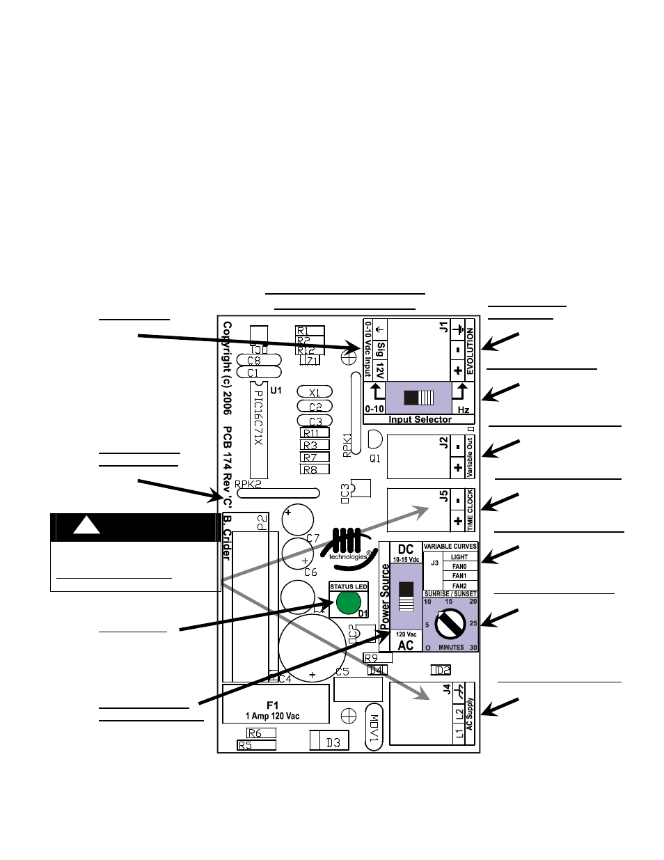
6.1 EV-VAR PCB 174 Board
(PCB rev C or later)
Layout and Setting Locations
Evolution Variable Output
PCB 174 rev C or Later
Time Clock Connections
See Section 6.5.
AC Supply Connections
See Section 6.2.
Variable Out Connections
See Section 6.7.
Evolution Input
Connections
See Section 6.4.
Variable Curves Jumpers
See Section 6.10.
!
DANGER
120 VAC is present when power
is applied.
DISCONNECT POWER prior to
setup or maintenance.
STATUS LED
See Section 6.8.
SUNRISE/SUNSET POT
See Section 6.9.
0-10Vdc Input
See Section 6.4.
Input Selector Switch
See Section 6.4.
POWER SOURCE
SELECTOR SWITCH
See Section 6.3.
PCB 174 Circuit
Board Revision