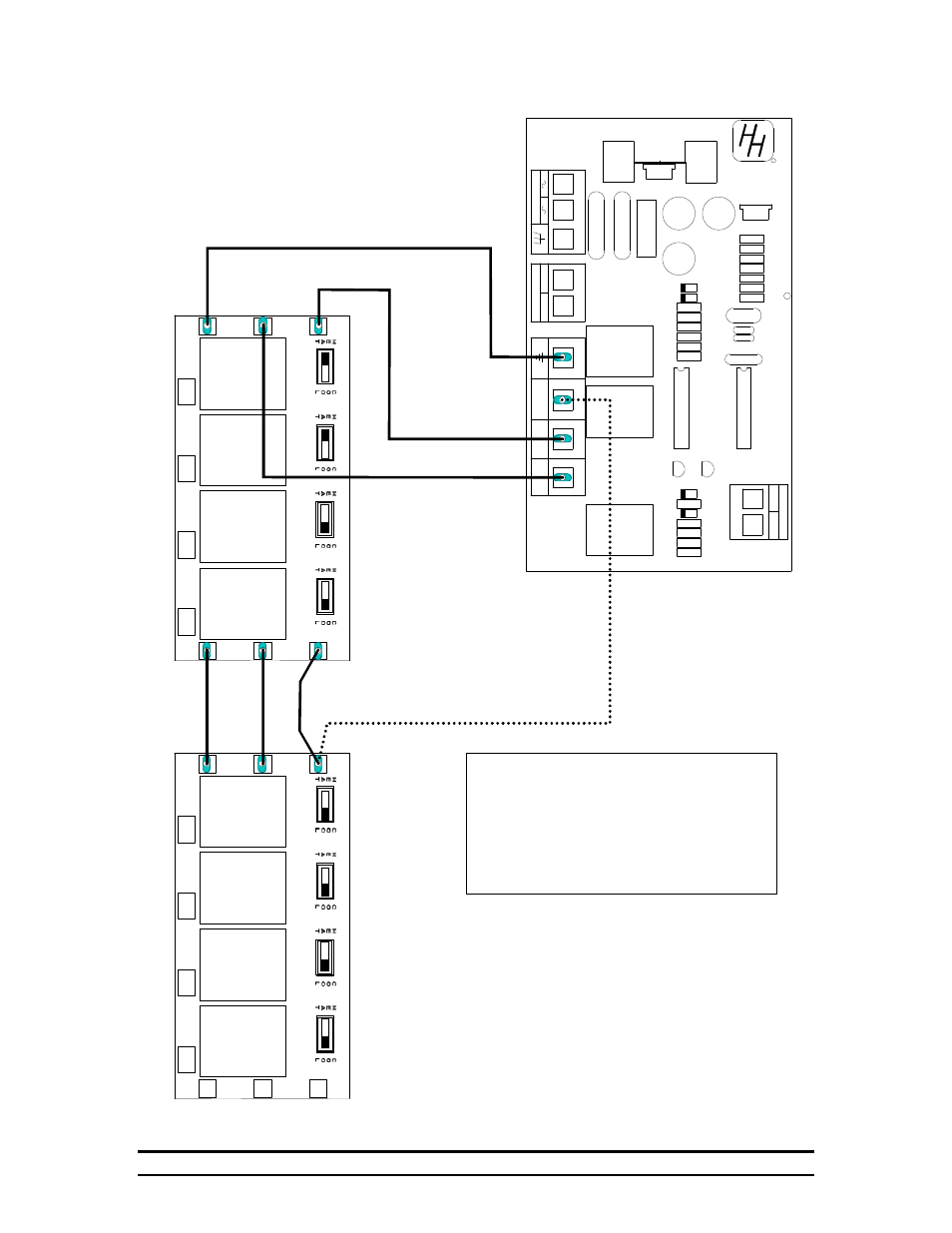
Wiring diagram for two stage cool back-up, Œ• œ, Contactor control systems 6 – Hired-Hand Contactor Control System (CCS): 4, 8, or 12 Stage User Manual
Page 8
Contactor Control Systems
6
STAGE
STAGE
STAGE
STAGE
COOL
HEAT
GND
COOL
HEAT
GND
5
6
7
8
STAGE
STAGE
STAGE
STAGE
COOL
HEAT
GND
COOL
HEAT
GND
1
2
3
4
HIRED-HAND
R
-
+
ALARM
AC
SENSOR
+
-
COOL 2
COOL 1
HEAT
Wiring Diagram for Two
Stage Cool Back-Up
When the back-up is wired in this manner,
and the switches are aligned as shown,
stages 3 and 4 would come on when
the back-up board calls for Cool 1.
When the back-up board calls for Cool 2
the remaining cool stages would start.
This board found on back of
CCS Panel door.
Œ
•
Œ
•
Remove the wire connecting the two relay boards
at the cool positions.
Install new wire from the backup board position labeled
cool 2, to the "COOL" position on the lower relay board..
See also other documents in the category Hired-Hand Equipment:
- Polar Cool: Portable Evaporative Cooling System (22 pages)
- Polar Cool: External Control Box (4 pages)
- Polar Cool: Pump & Float Replacement (2 pages)
- Polar Cool: PUMP REPLACEMENT (4 pages)
- Polar Cool: Wall Mount Kit (4 pages)
- Unitized Mega Cool (68 pages)
- Unitized Mega Cool: Square Bottom (63 pages)
- Mega-Cool: Square Reservoir (24 pages)
- Mega-Cool rev 6-09 (46 pages)
- Mega-Cool: Mega-Cool Pad Extender Kit (5 pages)
- Mega-Cool: Float Valve Replacement (1 page)
- Mega-Cool: Float Valve (Topaz) Replacement (1 page)
- Mega-Cool: In-Line Pump Motor Replacement (2 pages)
- Var-O-Matic (2 pages)
- System 1000 Power Vent (13 pages)
- System 1000 Power Vent (31 pages)
- System 500 Programs (Conventional Model) (5 pages)
- System 100 Variable Speed Controller (7 pages)
- System 500 Programs (Tunnel Model) (7 pages)
- System 1000 Power Curtain (17 pages)
- System 2000 AUTO TEMP (10 pages)
- System 2001 Power Curtain Controller (43 pages)
- System 500 Power Curtain Controller (31 pages)
- System 1000 Power Curtain Eight Stage Controller (34 pages)
- ICS-500 Environmental Controller (34 pages)
- Pressure Transducer Changeout (1 page)
- HH Software: HH.Net Router/Repeater (8 pages)
- HH Software: 900SS Wireless Network (10 pages)
- HH Software: Farm Manager (22 pages)
- HH Software: Data Shuttle Launch Pad (25 pages)
- Sens-O-Matic (Feed Hopper Switch) (2 pages)
- Manual Light Dimmer (2 pages)
- Electro Mechanical Controls (Relay-Switches): PHOTOHELIC POWER VENT (10 pages)
- Electro Mechanical Controls (Relay-Switches): PT Controller (9 pages)
- Electro Mechanical Controls (Relay-Switches): PC-DB Curtain Controller with DIF (6 pages)
- Electro Mechanical Controls (Relay-Switches): PC-DB Curtain Controller with Timer Override (7 pages)
- Electro Mechanical Controls (Relay-Switches): Photohelic Gauge (1 page)
- Feed Management System (15 pages)
- Contactor Control System (CCS): Triple Pole 16-Stage (7 pages)
- Contactor Control System (CCS): Vent Machine Override 3 Wire PowerTrak (1 page)
- Evolution 4000 Control System (86 pages)
- Evolution Series 1200: Variable Output With Override Pot (14 pages)
- Evolution Series 1200: Variable Output (12 pages)
- Evolution Series 1200 (64 pages)