Back-up system, Front panel, General description – Hired-Hand Contactor Control System (CCS): 4, 8, or 12 Stage User Manual
Page 6: Controls
Contactor Control Systems
4
J4
J5
VR4
H
E
A
T
CR4
SW4
C
O
O
L
VR3
H
E
A
T
CR3
SW3
C
O
O
L
VR2
C
O
O
L
RLY4
RLY3
COOL
August 26, 1991 L.Self
Copyright C 1991,1992
PCB 115 (REV 0)
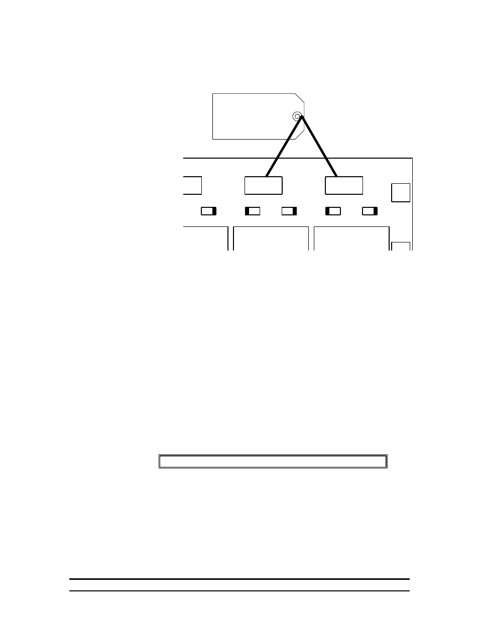
These switches
must be in the
proper position.
6.1.3.2.
Front Panel
The only controls on the outside of a standard contactor panel are the
“Auto/Off/On” toggle switches. These switch positions allow you to
select whether the stage will be on continuously, be turned on or off as
needed by the controller, or turned off unless needed by the back-up
system. An indicator light is provided for each stage to show at a glance
which stages are running.
6.2. Back-up System
6.2.1. General Description
The back-up system has its own sensor which allows the board to continuously monitor
house temperature separately from the controller. If this temperature should exceed the
limits set by the dials on the front of the Contactor Panel, the back-up system would
engage the appropriate equipment. (For example: If the temperature is below the low limit
setpoint, the back-up board would engage all heat stages.)
Note: If power to the back-up board is lost, all stages will turn on.
The back-up board allows for a two step cool stage engagement. For a description of the
two step cool stage option, see section 6.2.3.2. If you want to use the two step option,
you will need to change the wiring inside the panel. For a diagram, see the drawing on
page 6.
6.2.2. Controls
The back-up system has three controls: Two temperature limit knobs, and a reminder
reset button. The temperature knobs are labeled “High Limit” and “Low Limit”.