C5-9, Lmounting procedure of antenna – Yokogawa YFGW510 User Manual
Page 41
C5-9
IM 01W02E01-01EN
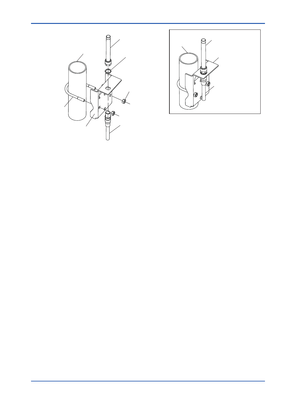
Bracket
ISA100.11a antenna
Antenna Extension Cable
2-inch pipe
U Bolt
Nut
Nut
Bracket
Antenna Extension Cable
ISA100.11a antenna
2-inch pipe
FC0507.ai
Figure C5-7 Fastening remote antenna
l
Mounting procedure of antenna
1. Fix the bracket by U-bolt and nut to 2-inch pipe.
2. Fix the antenna extension cable to the bracket using the provided nut with a torque of 6 to
7 N∙m as shown in the Figure C5-7. Use the nut which is attached to the antenna extension
cable.
3. Screw the antenna into the antenna connector of the antenna extension cable on the
bracket.
Tighten the antenna connector with a torque of 2 to 3 N∙m.
4. Protect the connection with a tape as necessary. For details of the protection, see “5.4.1
Mounting ISA100.11a antenna to YFGW510”.
n
Antenna wiring and improvement of environment resistance
l
Specification for antenna extension cable
(Only by order of option)
• Specification: 8D-SFA(PE)
• Outside diameter: 11.1 mm
• Minimum bend radius: 67 mm (when fixing)
167 mm (when wiring)
• Cable end treatment: N type connector, one end is male and the other is female.
* “When fixing” shows the bending radius for fixing (the state is maintained for a long time).
“When wiring” shows the bending radius while checking the wiring position. This bending
radius is set larger than that for fixing in order to prevent damage to the cable because the
cable is likely to be repeatedly bent when checking the final wiring position.