Part-c. installation, C1. installation environment, C1-1 – Yokogawa YFGW510 User Manual
Page 25: Important
C1-1
IM 01W02E01-01EN
PART-C. INSTALLATION
This part describes installation for YFGW510.
Follow the steps below to use of the product.
1. Installation of YFGW510
2. Wiring of the power supply, grounding cable, signal cables and mounting/wiring of
antenna(s)
C1. Installation Environment
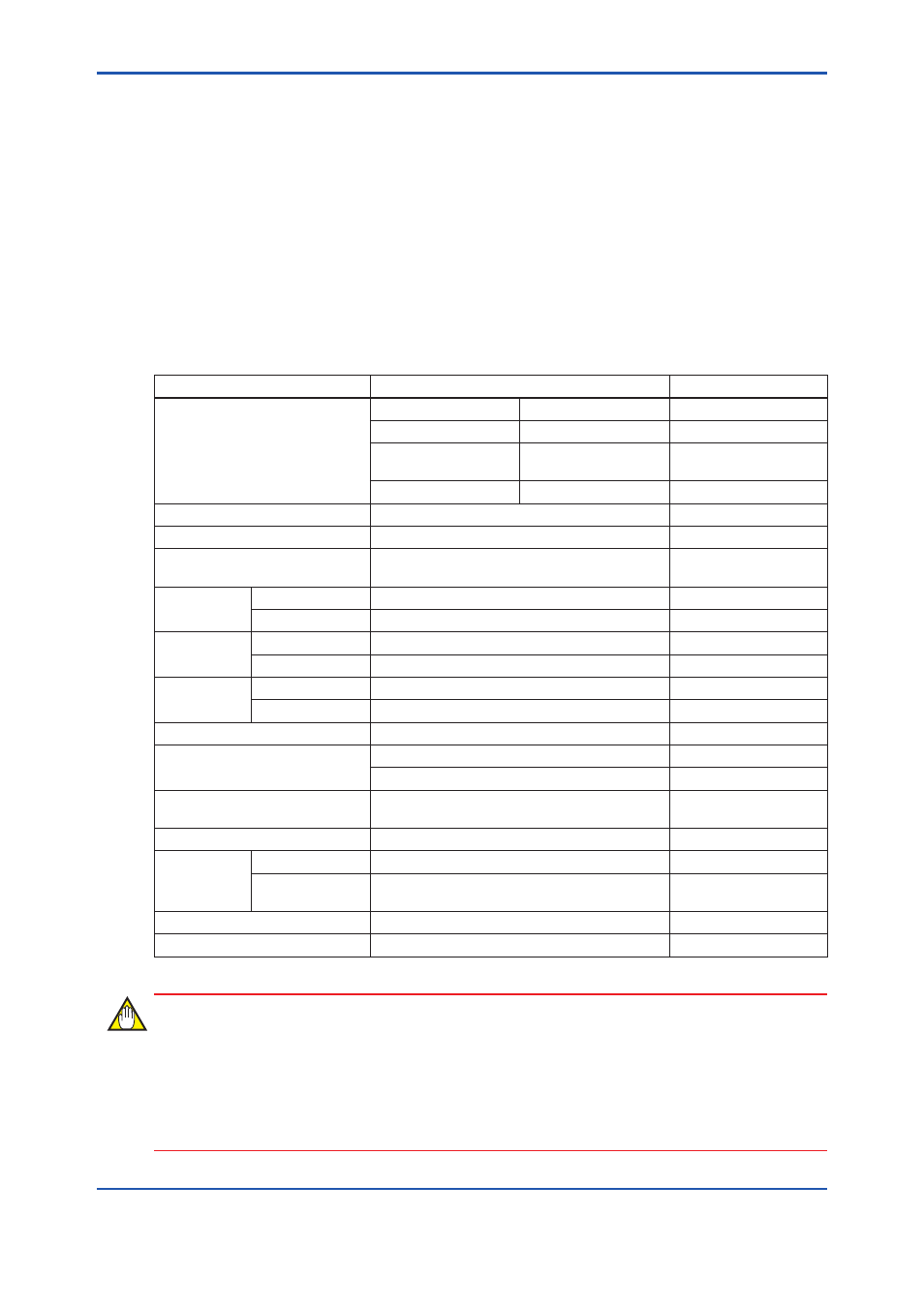
YFGW510 should be installed in appropriate conditions to ensure its stable operation.
The table below shows details of the installation environment for YFGW510.
Item
Environment
Note
Power supply
Rated voltage
24 V DC
Voltage range
10 to 26.4 V DC
Momentary power
failure
1 ms or less (instant
disconnection)
Ripple ratio
1%p-p or less
Terminal
M4 screw terminal (power supply and ground)
Maximum power consumption
3.5 W
Grounding
Class D grounding (100 Ω or less)
No sharing with other
devices
Temperature
range
Operating
-40 to 65°C
Transport/storage -40 to 85°C
Humidity
range
Operating
0 to 100% RH (No condensation)
Transport/storage 0 to 100% RH (No condensation)
Temperature
gradient
Operating
±10°C/h or less
JEIDA29 class B
Transport/storage ±20°C/h or less
Protection degree
IP66
IEC529
Vibration resistance
Displacement amplitude: 0.21 mm (10 to 60 Hz)
Acceleration amplitude: 3 G (60 to 2000 Hz)
Shock resistance
50 G 11 ms (de-energized, with half-sine wave
pulse in three directions)
IEC68-2-27
Altitude
3000 m or less
Noise
resistance
Electric field
3 V/m or less (80 MHz to 1 GHz)
Electrostatic
discharge
4 kV or less (contact discharge), 8 kV or less
(aerial discharge)
Cooling
Natural air cooling
Mounting
2-inch pipe
With dedicated brackets
IMPORTANT
• Avoid exposing the YFGW510 to direct sunlight.
• Avoid iron flakes, carbon particles, or any other type of dust that are conductive.
• Avoid existence of corrosive gases such as hydrogen sulfide, sulfurous acid gas, chlorine,
and ammonia.