14 sensor trim, 14 sensor trim -12 – Yokogawa Wireless Temperature Transmitter YTA510 User Manual
Page 19
IM 01C50T03-01E
3-12
3. OPERATION
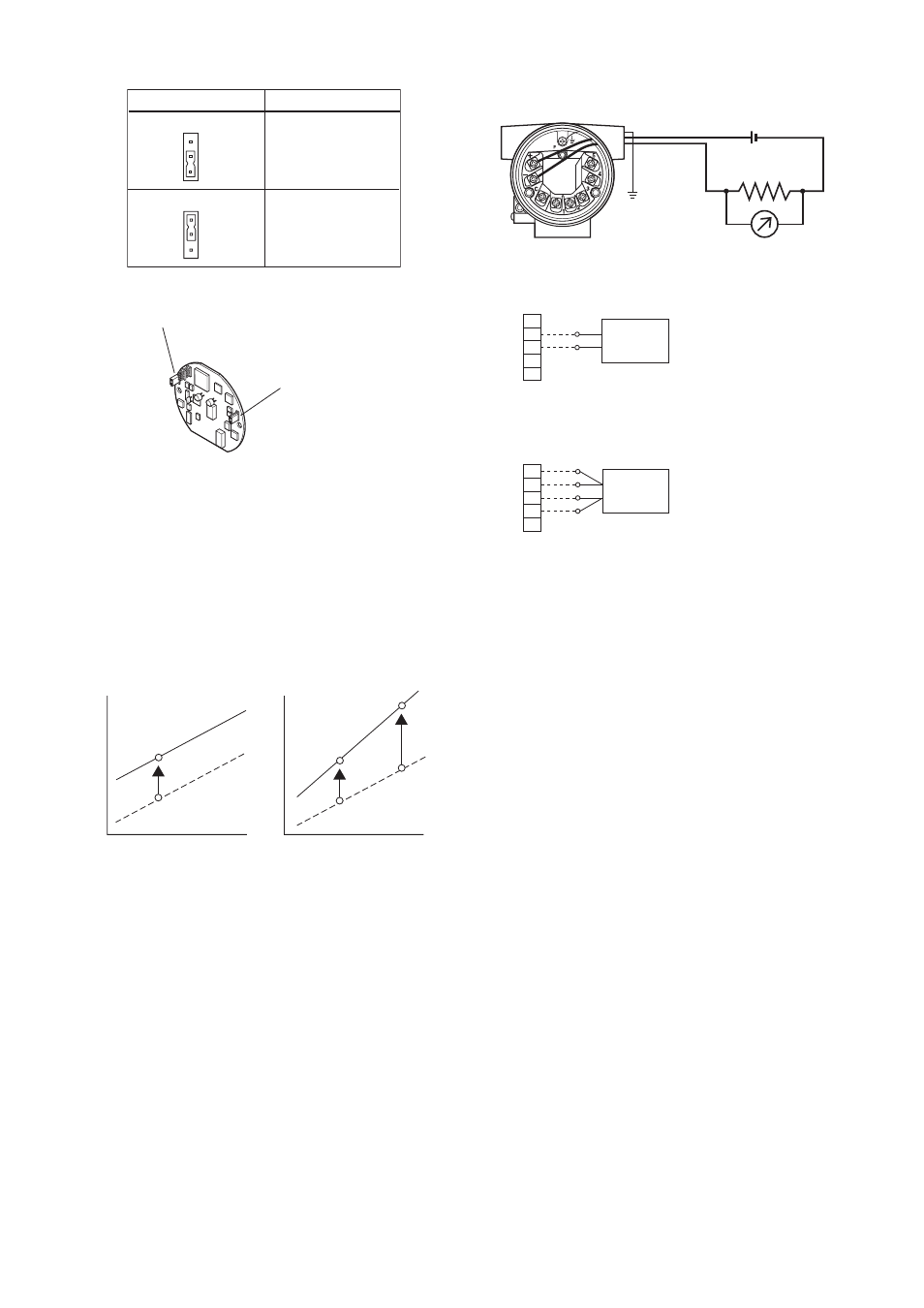
Pin position of SW2
Write Protect Status
Y
N
No
F0355.EPS
W P
Yes
Y
N
W P
SW2
SW2
SW2
Hardware Write Protect
SW1
Burnout output direction
upon hardware failure
CPU Assembly
Figure 3.3
SW2 setting
3.2.14 Sensor Trim
Each YTA transmitter is factory-characterized based on
the standard sensor curve and uses the information to
produce a process variable output. The sensor trim
function is used to adjust to the transmitters internal
interpretation of the input signal.
Input
ZERO
One point trim
Input
ZERO
GAIN
Two points trim
F0310.EPS
Output
Output
Figure 3.4
Trim function images
(a) Zero/Gain Point Adjustment
J07: IN TRIM MODE
J10: SNSR1 ZERO, J20: SNSR1 GAIN
K10: SNSR2 ZERO, K20: SNSR2 GAIN ...YTA320 only
1) Connect the temperature transmitter and the
calibration device as shown in Figure 3.5 and warm
up for at least three minutes.
a. Wiring of power supply and output
b. Example of wiring of thermocouple
or DC voltage input (1-input type)
F0311.EPS
+ Output signal
–
Load resistance
DC voltage generator
or thermocouple
Voltmeter
1
2
3
4
5
c. Example of wiring of thermometer resistor
4-wire type (1-input type)
Variable resistor
or thermometer resistor
1
2
3
4
5
(+)
(A)
(B)
(B)
(A)
(–)
Figure 3.5
Example of wiring for calibration equipment
2) Check the sensor type with the D: parameter.
3) Select the input trimming mode in J07:IN TRIM
MODE. The following selections are offered.
V.R./ZERO&GAIN
V.R./ZERO
TEMP/ZERO&GAIN
TEMP/ZERO
Select “V.R./ZERO&GAIN” or “V.R./ZERO” when
the calibration device is DC voltage generator or
Variable resistor, or select “TEMP/ZERO&GAIN”
or “TEMP/ZERO” when the device is Temperature
sensor.
4) Perform zero-point adjustment.
• When the input trimming mode is “V.R./
ZERO&GAIN” or “V.R./ZERO”, apply the value
for the zero-point shown in the Table 3.1 depend-
ing on the specified sensor type. Wait until the
input from the calibration device becomes stable.
• When the input trimming mode is “TEMP/
ZERO&GAIN” or “TEMP/ZERO”, expose the
temperature sensor to calibration temperature for
the zero-point. Wait until the input from the
temperature sensor becomes stable.