9 burn out function, 10 reverse output function, 11 sensor backup function (for model yta320) – Yokogawa Wireless Temperature Transmitter YTA510 User Manual
Page 17: Burn out function -10
IM 01C50T03-01E
3-10
3. OPERATION
3.2.9
Burn Out Function
(a) Sensor burn out
Configure the burn out mode in the case of sensor
failure or disconnection. When the sensor failure is
detected, the transmitter will output one of the follow-
ing values.
F40: BURN OUT
Select from the followings:
LOW
: Outputs 3.6 mA (-2.5%)
HIGH
: Outputs 21.6 mA (110%)
USER mA
: Output user set value in mA.
Settable 3.6 to 21.6 mA in F41
USER %
: Output user set value in %.
Settable -2.5 to 110 % in F41
OFF
: The burn out output is NOT
defined
F41: BURN OUT VAL
When “USER mA” or “USER %” is selected at
F40:BURN OUT, F41:BURN OUT VAL is displayed.
The output value setting range is 3.6 to 21.6 mA (-2.5
to 110%).
ESC
SET
F40:BURN OUT
HIGH
DIAG
PRNT
ESC
PARAM
F40:BURN OUT
USER mA
F41:BURN OUT VAL
21.6 mA
F50:TX FAILURE
HIGH
DEL
CLR
ESC
SET
F41:BURN OUT VAL
21.6 mA
+ 20.8
DIAG
PRNT
ESC
PARAM
F40:BURN OUT
HIGH
F50:TX FAILURE
HIGH
F60:SELF CHECK
GOOD
DATA
DATA
F0307.EPS
●
Example: Setting output to 20.8 mA in the event of
sensor burn out
1. Select F40: BURN OUT and
press [ENTER].
2. Select "USER mA" and press
[ENTER] twice.
3. Press [OK].
4. Select F40: BURN OUT VAL
and press [ENTER].
5. Set “20.8” and press [ENTER]
twice.
6. Press [OK].
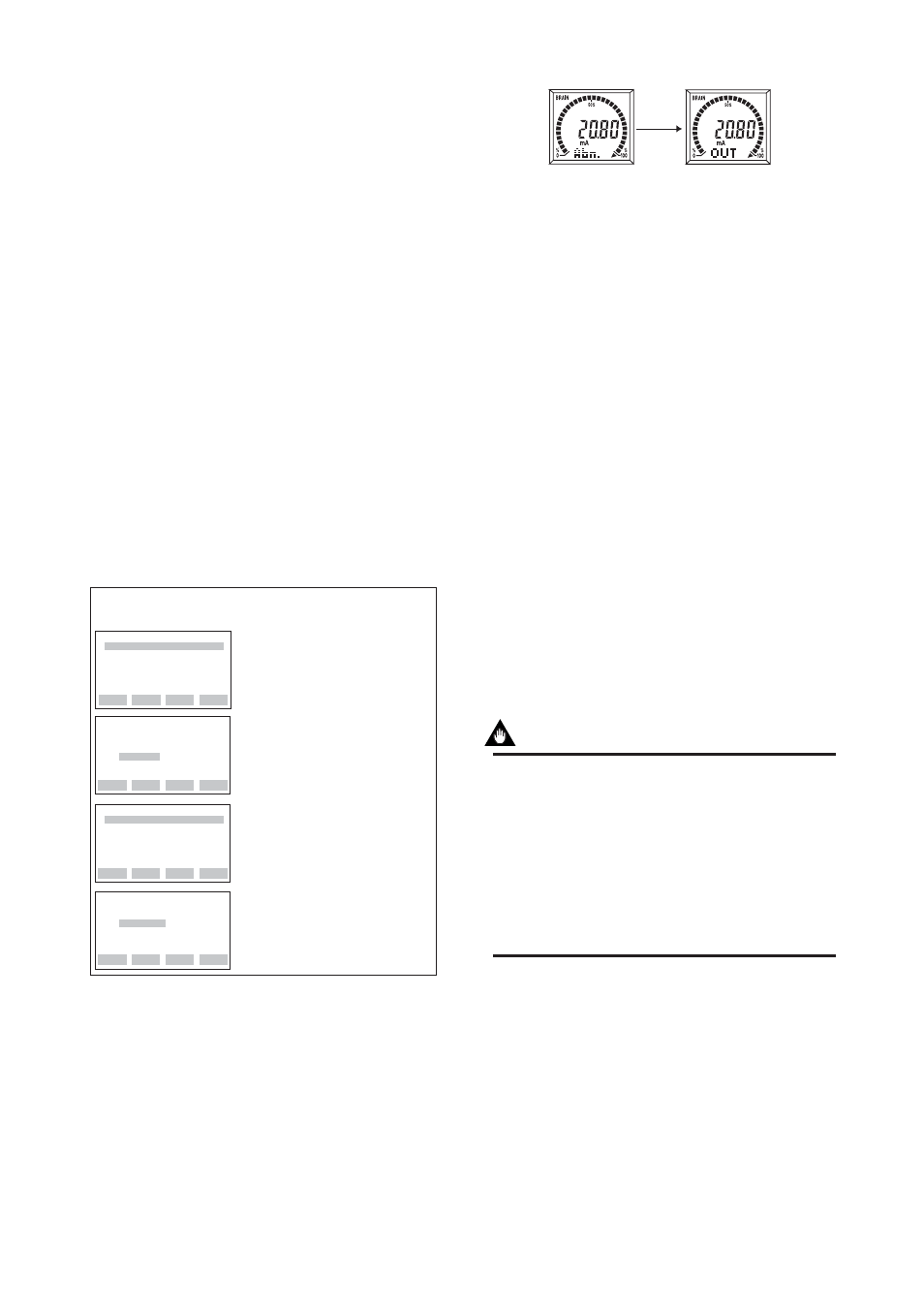
During sensor burn out time, the Sensor1 failure or the
Sensor2 failure error message is generated. (See
Section 4.1.1 for details.)
If the transmitter is equipped with the integral indica-
tor, the LCD displays “Abn.” and “OUT” as shown in
Figure 3.2.
F0308.EPS
Displays "Abn."
Displays "OUT."
Figure 3.2
Integral Indicator Display in Sensor Burn Out
(b) Confirming the output direction if Hard-
ware error occurs
F50: TX FAILURE
The output status of the transmitter in hardware failure
is set by using a jumper on the CPU assembly. (See IM
01C50B01-01E section 3.2) The current setting can be
checked in parameter D50: TX FAILURE.
HIGH
: When an error occurs,
110%(21.6mA) or higher is
output.
LOW
: When an error occurs,
-5%(3.2mA) or lower is output.
3.2.10 Reverse Output Function
H10: REVERSE OUT
To reverse the direction for a 4 to 20 mA DC output
relative to input.
3.2.11 Sensor Backup Function
(For Model YTA320)
IMPORTANT
To use sensor backup function, the following
conditions must be met.
• “Sensor1” is mapped as the PV at B10: PV is.
• “Sensor2” is mapped as the SV at B20: SV is.
• “Sensor1” and “Sensor2” are both correct
input status.
• “HIGH, LOW, User mA, or User %” is se-
lected in the sensor burnout
parameter setting at F40: BURN OUT
The sensor backup command sets the transmitter to
automatically use Sensor2 as PV if Sensor1 fails.
When the transmitter is in the Sensor Backup operation
and switches to Sensor2, there will be no disruption in
the 4 to 20 mA output. The error code for Sensor1
failure is shown on the integral indicator, and also the
error message is sent to the BT200 that the Sensor1
failed and the sensor backup has been in operation. In
case Sensor2 fails during the backup operation, the