2 process variables mapping, Process variables mapping -5, Showing that a process variable is not assigned – Yokogawa Wireless Temperature Transmitter YTA510 User Manual
Page 12
IM 01C50T03-01E
3-5
3. OPERATION
DATA
DIAG
PRNT
ESC
PARAM
D10:SENSOR1 TYPE
Pt200 (IEC751)
D20:SENSOR WIRE
3 WIRE
D40:SENSOR1 TEMP
23.56 degC
ESC
SET
D10:SENSOR1 TYPE
Pt200 (IEC751)
TYPE B (IEC584)
TYPE W3(ASTM988)
TYPE W5(ASTM988)
TYPE E (IEC584)
TYPE J (IEC584)
TYPE K (IEC584)
TYPE L(DIN43710)
TYPE N (IEC584)
TYPE R (IEC584)
TYPE S (IEC584)
TYPE T (IEC584)
TYPE U(DIN43710)
Pt100 (IEC751)
Pt200 (IEC751)
Pt500 (IEC751)
JPt100 (JIS)
Ni120 (STI INC)
Cu (SAMA RC21-4)
ohm
mV
Non Connection
ESC
SET
D20:SENSOR1 WIRE
3 WIRE
<3 WIRE >
<4 WIRE >
<2 WIRE >
<1>
<2>
<3>
F0302.EPS
●
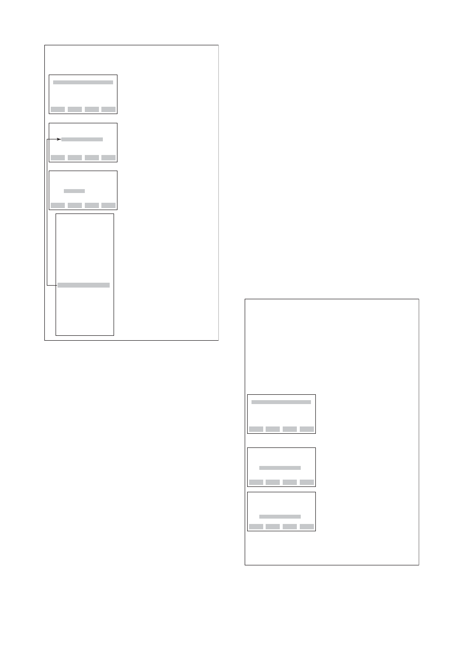
Example: Set Pt 100 and 4-wire type to Sensor1.
(model YTA320)
1. Select D: SET SENSOR1 to go
to the screen (1).
2. Select “D10” and press
[ENTER] to go to the
screen (2).
3. Select “Pt100” and press
[ENTER] twice.
4. Check that “Pt100” has been
set and press [OK].
5. To set the number of wire
connections, select
D20 and press [ENTER].
6. Select “4 WIRE” and press
[ENTER] twice.
7. Press [OK].
Note: D40 indicates input values of
the sensor based on the
settings at D10 and D20.
3.2.2
Process Variables Mapping
Process variable mapping;
B10: PV is, B20: SV is, B30: TV is, B40: 4V is
Process variables can be assigned as the primary
variable(PV), the secondary variable(SV), the tertiary
variable(TV), and the quaternary variable(4V). The PV
always outputs a 4 to 20mA DC analog signal corre-
sponding to Lower Range Value and Upper Range
Value. Mapping process variables to the SV, TV, and
4V is optional.
The following items can be mapped as the process
variables.
Sensor1
: Sensor1 input value.
Sensor2
: Sensor2 input value.
DIFFERENCE
*1,*2,*4
: Difference between
Sensor1 and Sensor2.
(Sensor1-Sensor2 or
Sensor2-Sensor1; speci-
fied in B05: SET DIFF)
AVERAGE
*1,*4
: Average of Sensor1 and
Sensor2.
[(Sensor1 + Sensor2)/2]
Sensor1-Term
*4,*5
: Difference between
Sensor1 and terminal
temperature
Sensor2-Term
*1,*4,*5
: Difference between
Sensor2 and terminal
temperature
Terminal Temp
: Terminal temperature
Not used
*3
: Showing that a process
variable is not assigned.
*1: This item is displayed only when the YTA320 2-input
temperature transmitter is used.
*2: The setting in B05 applies to the PV, SV, TV, and 4V.
*3: “Not used” is not displayed for B10 since the PV
requires process variable mapping.
*4: When this item is selected, the sensor types to be set
for D10(Sensor1) and E10(Sensor2) should be
selected from any one of the following three groups;
Temperature sensor(T/C and RTD), DC voltage or
resistance. The combination(for example, temperature
sensor and DC voltage input) would cause an incorrect
computation due to the different unit system and is not
allowed.
*5: When this item is selected, DC voltage and resistance
input should not be set for D10(Sensor1) or
E10(Sensor2).
F0303.EPS
DATA
DIAG
PRNT
ESC
PARAM
B05:SET DIFF
Sensor1-Sensor2
B10:PV is
Sensor1
B11:PV UNIT
degC
ESC
SET
B05:SET DIFF
Sensor1-Sensor2
ESC
SET
B10:PV is
Sensor1
1. Set the content of
“DIFFERENCE” for the
difference between Sensor1
and Sensor2.
Select B05: SET DIFF and
press [ENTER]
2. Select “Sensor2 - Sensor1” and
press [ENTER] twice.
3. Press [OK].
4. Select B10: PV is and press
[ENTER] for PV mapping.
5. Select “DIFFERENCE” and
press [ENTER] twice.
6. Press [OK].
●
Example: Use two temperature sensors to map the
difference (Sensor2-Sensor1) between Sensor1
and Sensor2 to the PV (the primary variable).
Before mapping the process variable, complete the
setting of the temperature sensor to be connected
to Sensor1 and Sensor2.
Sensor1 setting: D10: SENSOR1 TYPE, D20:
SENSOR1 WIRE
Sensor2 setting: E10: SENSOR2 TYPE, E20:
SENSOR2 WIRE
If the temperature sensor is correctly connected to Sensor1
and Sensor2,
the setting content is reflected on A10: PV.