2 setting parameters, 1 sensor configuration, Setting parameters -4 – Yokogawa Wireless Temperature Transmitter YTA510 User Manual
Page 11: Sensor configuration -4
IM 01C50T03-01E
3-4
3. OPERATION
3.2 Setting Parameters
3.2.1
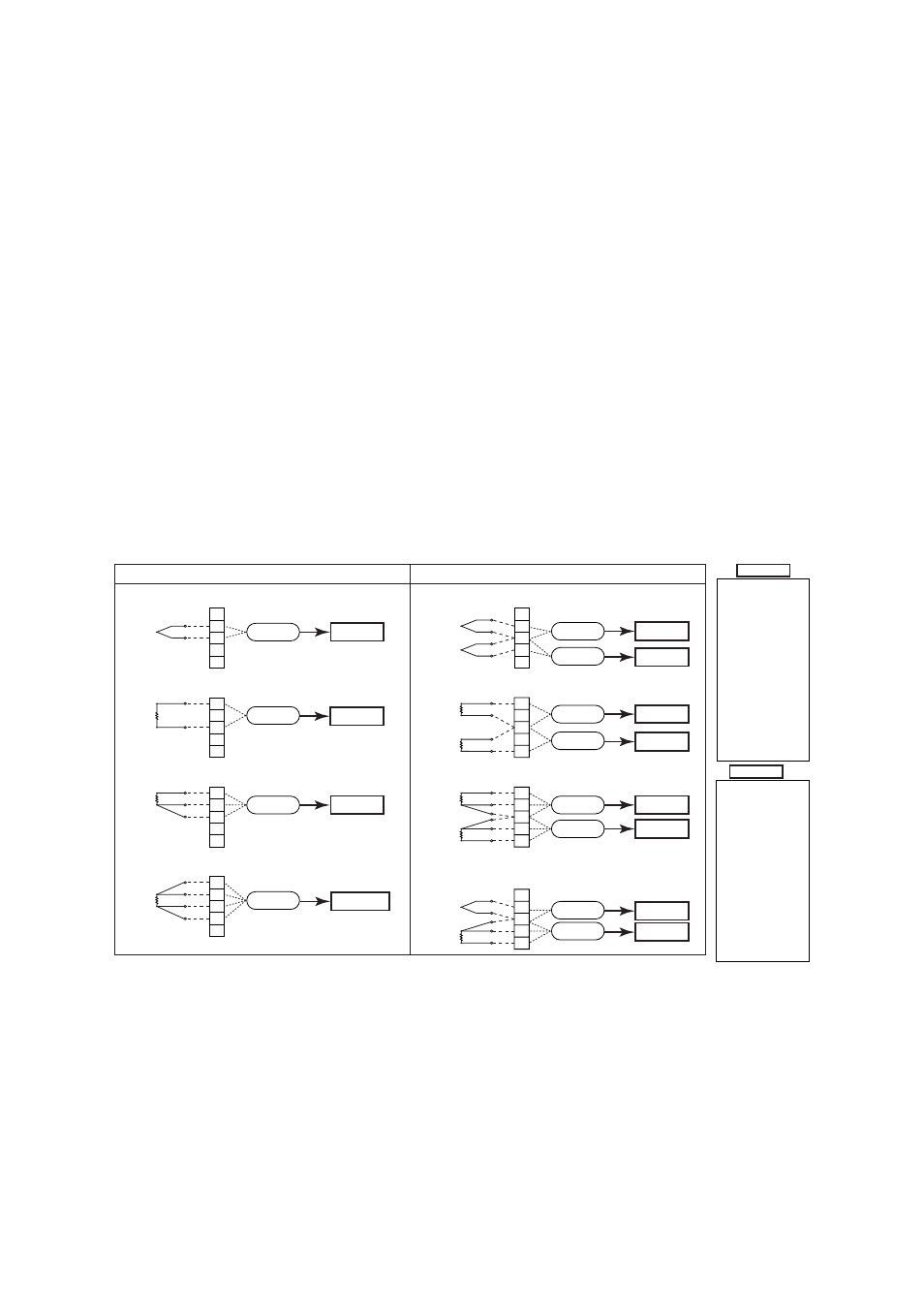
Sensor Configuration
When the sensor type or the number of wire connec-
tions changes, the following parameters must be reset.
Sensor type setting;
D10: SENSOR1 TYPE, E10: SENSOR2 TYPE
Wire connections setting;
D20: SENSOR1 WIRE, E20: SENSOR2 WIRE
Figure 3.1 diagram shows the wire connections to the
input terminals of the transmitter and sensor type
selections for the parameters in each connection case.
Note that TCs and mV are categorized as Group A and
RTDs and ohm as Group B.
Check the connections between the input terminals and
temperature sensors and set the correct sensor type and
the number of wire connections for the parameters.
Thermocouple and DC voltage (TC & mV)
Resistance thermometer(RTD) and resistance (2-wire type)
1-input model YTA110, YTA310, and YTA320
2-input model YTA320
1
2
3
4
5
1
2
3
4
5
1
2
3
4
5
1
2
3
4
5
(–)
(+)
(B)
(A)
(B)
(B)
(A)
(B)
(A)
(A)
(B)
Thermocouple(TC) &
Resistance thermometer(RTD) and resistance (3-wire type)
1
2
3
4
5
(–)
(+)
(+)
F0301.EPS
Sensor1
Sensor1
Sensor1
Sensor1
1
2
3
4
5
(B1)
(A1)
(B2)
(A2)
Sensor2
Sensor1
1
2
3
4
5
(B1)
(B1)
(A1)
(B2)
(B2)
(A2)
Sensor2
Sensor1
Sensor2
Sensor1
1
2
3
4
5
(–)
(+)
(A)
(B)
(B)
Sensor2
Sensor1
Resistance thermometer(RTD) (4-wire type)
Resistance thermometer(RTD) and resistance (3-wire type)
Thermocouple and DC voltage (TC & mV)
Resistance thermometer(RTD) and resistance (2-wire type)
Resistance thermometer(RTD) and resistance (3-wire type)
Group A
Group B
Group B
*
Group B
Group A
Group A
Group A
Group B
Group B
Group B
Group B
Group B
TYPE B (IEC584)
TYPE W3 (ASTM988)
TYPE W5 (ASTM988)
TYPE E (IEC584)
TYPE J (IEC584
TYPE K (IEC584)
TYPE L (DIN43710)
TYPE N (IEC584)
TYPE R (IEC584)
TYPE S (IEC584)
TYPE T (IEC584)
TYPE U (DIN43710)
Pt100 (IEC751)
Pt200 (IEC751)
Pt500 (IEC751)
JPt100 (JIS)
Ni120 (STI INC)
Cu (SAMA RC21-4)
ohm
mV
TYPE B (IEC584)
TYPE W3 (ASTM988)
TYPE W5 (ASTM988)
TYPE E (IEC584)
TYPE J (IEC584
TYPE K (IEC584)
TYPE L (DIN43710)
TYPE N (IEC584)
TYPE R (IEC584)
TYPE S (IEC584)
TYPE T (IEC584)
TYPE U (DIN43710)
Pt100 (IEC751)
Pt200 (IEC751)
Pt500 (IEC751)
JPt100 (JIS)
Ni120 (STI INC)
Cu (SAMA RC21-4)
ohm
[
* Only for 2 or 3-wire type]
mV
Group A
Group B
*
: Without ohm
Figure 3.1
Input terminal wire connection diagram and sensor type categories
Sensor type selection
Thermocouple
TYPE W3, W5 (ASTM988)
TYPE B, E, J, K, N, R, S, T
(IEC 584)
TYPE L, U (DIN 43710)
Resistance thermometer
Pt100, Pt200, Pt500
(IEC 751)
[2-, 3- or 4-wire]
JPt100 (JIS)
Ni120 (STI INC), Cu
(SAMA RC21-4)
DC voltage
mV
Resistance
ohm [2- or 3-wire]