Yokogawa Wireless Temperature Transmitter YTA510 User Manual
Page 15
IM 01C50T03-01E
3-8
3. OPERATION
mA
: Displays output value in mA
%
: Displays output value in %
mA, %
: Displays output value in
mA and % alternately
INHIBIT
: The output value is not
displayed
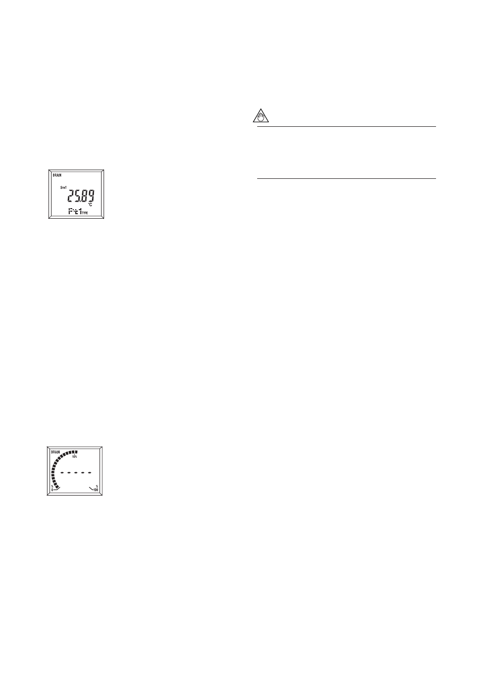
(c) Display sensor type/number of wire
connections
M30: MATRIX DISP
Used to select the input sensor type
and the number of wire connec-
tions to be displayed on the LCD
indicator. The displays of these
items are synchronized with the
process variable displays selected
at M10. Specifying “INHIBIT”
under M10 disables the function of M30 for the
display.
PROCESS
: Displays process variables
(PV, SV, TV, or 4V.)
TYPE
: Displays sensor type
WIRE
: Displays number of wire
connections
PROCESS, TYPE : Displays process and
sensor type alternately
TYPE, WIRE
: Displays sensor type and
number of wire
connections alternately
INHIBIT
: the sensor type and the
number of wire
connections is not
displayed
(d) Display output bar graph
M40: BAR GRAPH
Used to select output bar graph
display ON/OFF.
SHOW
: Displays analog output bar
graph
INHIBIT
: No bar graph display
(e) Select a cycle speed for display
M50: DISP UPDATE
Used to select the update rate for the display on the
LCD indicator. Process variables, output values, and
error codes are displayed using this cycle speed.
FAST
: 1/2 of the normal cycle
speed
NORMAL
: Normal cycle speed
SLOW
: 1.5 times of the normal
cycle speed
NOTE
When operating under –10
°
C(14
°
F), the display
response time may be reduced. In such a case,
set the display cycle speed to “NORMAL” or
“SLOW.”
F03293
Displays PV value and
sensor type
F03292
Displays bar graph.