7 forced output function, 8 integral indicator display function, Forced output function -7 – Yokogawa Wireless Temperature Transmitter YTA510 User Manual
Page 14: Integral indicator display function -7
IM 01C50T03-01E
3-7
3. OPERATION
Memo
O10: MEMO1, O20: MEMO2
Up to sixteen alphanumeric characters can be entered.
Description
O30: DESCRIPTOR
Up to sixteen alphanumeric characters can be entered.
Date
O40: DATE
Six numeric values can be entered. Only a date
recording function is provided; no internal clock
function is provided, thus the date is not updated.
3.2.7
Forced Output Function
G10: OUTPUT MODE, G20: OUPUT VALUE
This feature can be used to output a fixed current from
3.6 mA (-2.5%) to 21.6 mA (110%) for loop checks.
F0305.EPS
DATA
DIAG
PRNT
ESC
PARAM
G10:OUTPUT MODE
AUTOMATIC MODE
G60:SELF CHECK
GOOD
DATA
DIAG
PRNT
ESC
PARAM
G10:OUTPUT MODE
MANUAL MODE mA
G20:OUTPUT VALUE
4 mA
C60:SELF CHECK
GOOD
DEL
CLR
ESC
SET
G20:OUTPUT VALUE
4 mA
+ 16
FEED
NO
OK
SET
G20:OUTPUT VALUE
16 mA
ESC
SET
G10:OUTPUT MODE
AUTOMATIC MODE
"F.O." lit on.
●
Example: Outputting 16 mA (75%) constant current
1. Select G10: OUTPUT MODE
and press [ENTER].
2. Set "MANUAL MODE mA."
3. G20: OUTPUT VALUE is
displayed.
Select G20: OUTPUT VALUE
and press [ENTER].
4. Set "16."
5. Pressing [ENTER] twice outputs
a constant current.
If the transmitter is equipped
with the integral indicator, the
LCD displays F.O.
6. Press [OK].
IMPORTANT
• Manual mode output is held for approximately
10 minutes and then released automatically
after the time has elapsed. Even if the BT200
power supply is turned off or the communica-
tion connector is disconnected during the test,
it is held for approximately 10 minutes.
• To release the test output immediately, set
“AUTOMATIC MODE” at G10 as seen in the
figure above or turn off the transmitter.
3.2.8
Integral Indicator Display Function
If the transmitter is equipped with the integral indica-
tor, the following items can be displayed in parameter
settings.
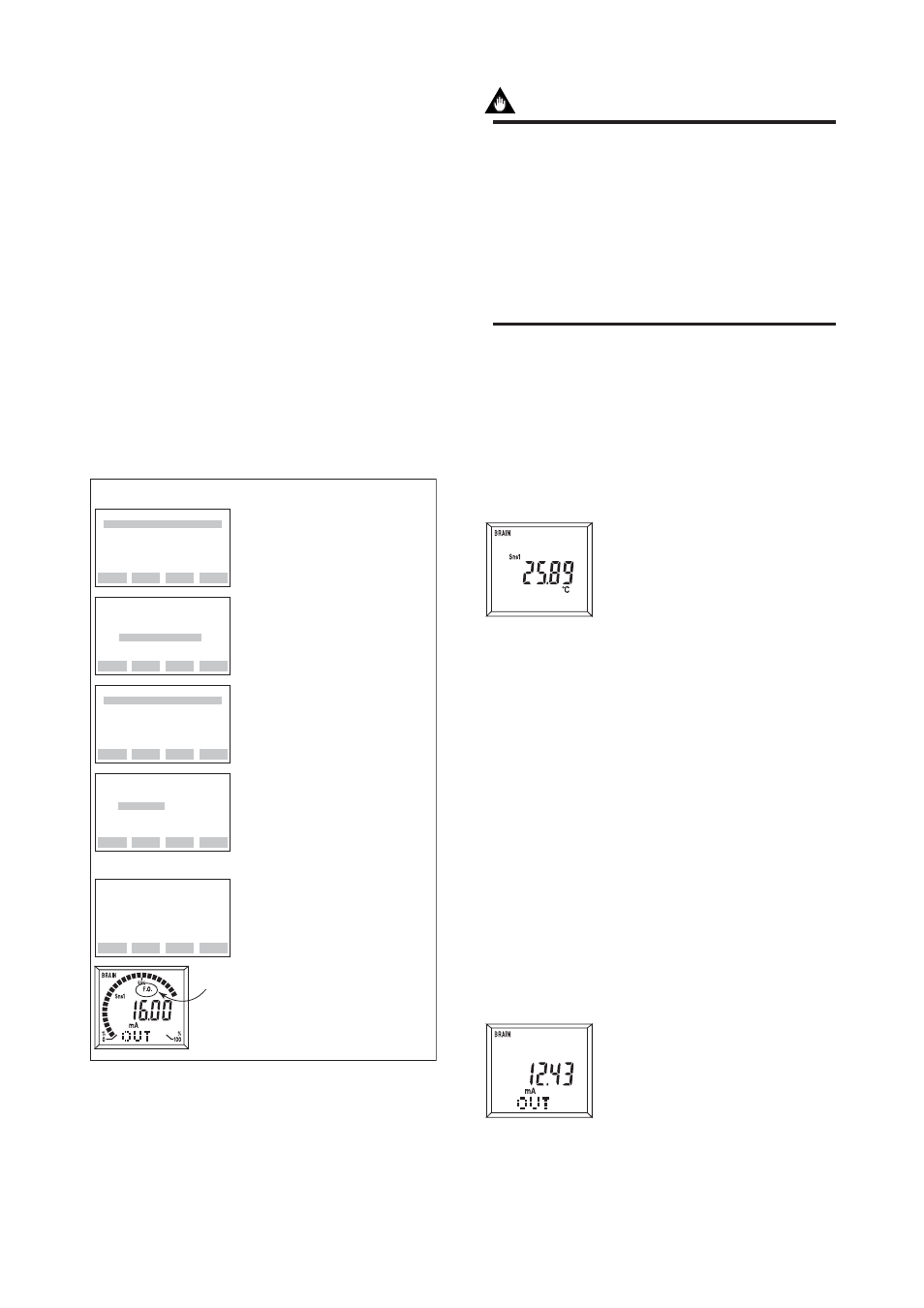
(a) Display process variable
M10: PROCESS DISP
Used to select the process variable
to be displayed on the LCD
indicator. If more than one process
is selected, they are displayed in
sequence as the display update
cycles. The appropriate unit is also
displayed for each process variable.
Also, if the output value is selected at M20, the process
variable and output value are displayed alternately.
PV
: Displays PV value
SV
: Displays SV value
TV
: Displays TV value
4V
: Displays 4V value
PV, SV
: Displays PV and SV
value alternately
PV, SV, TV
: Displays PV, SV and TV
value alternately
PV, SV, TV, 4V
: Displays PV, SV, TV, and
4V value alternately
INHIBIT
: The process variable is
not displayed.
(b) Display output value
M20: %/mA DISP
Used to select the output indica-
tions to be displayed on the LCD
indicator. If two output indications
are selected, they are displayed in
sequence as the display update
cycles.
F03291
Displays PV value.
F03292
Displays output value.